


10
4.1 GENERAL. This section contains troubleshooting
data for the Model 430 Sensor Assembly.
4.2 TROUBLESHOOTING THE MODEL 430
DISSOLVED OXYGEN SENSOR. The majority of
problems encountered in DO systems are because the
sensor is either improperly maintained or has an inter-
nal leakage causing improper temperature compen-
sator resistance and high impedance current paths
between elements of the sensor.
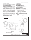
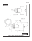
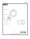
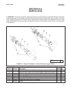
Disassemble the sensor completely by unscrewing the
reservoir retainer and pulling the reservoir housing
assembly straight out (refer to Figure 5-2). The mem-
brane may have dried onto the gold cathode. Soak this
loose with water as scraping will damage the gold tip.
Clean all the parts with clean water and dry them.
Check for visible damage (i.e., cracks, deep cuts, bro-
ken silver wires). Perform the following checks with an
ohmmeter. Check T.C. resistance between the green
and white wires. It should be 100K ohms at 25°C or per
the Temperature/Resistance Chart. Check continuity
between the red wire and the silver anode, and
between the black wire and the gold cathode (be care-
ful not to scratch the gold). Perform a high meg check
between the following (100 meg ohms minimum):
Shield to Black or Red or Green. If everything checks
O.K., the sensor should function after a proper
recharge. If the silver anode appears oxidized, it may
be cleaned with wet or dry 400 sandpaper. Also brush
the gold tip two or three times with the 400 sandpaper
in one direction only. Follow the recharge directions in
Section 3.2.
4.3 BENCH TESTING. Soak the electrode for 24 hours
with polarizing voltage applied (instrument), then air
calibrate to check for a response.
CAUTION
Care should be taken not to damage the
membrane made of “Teflon”.
1. Low readings and inability to calibrate are
generally the result of a coated membrane
and usually can be restored to service by
cleaning the sensor. Clean a coated mem-
brane by gently wiping the membrane with a
soft cloth or tissue.
1
Reg. U.S. Pat. Office for du Pont’s fluorocarbon resins.
2. Readings offscale and inability to calibrate
are usually caused by a damaged mem-
brane. If this is the case, replace the mem-
brane.
3. To check the membrane made of “Teflon”,
connect the negative (—) lead of an ohm-
meter to the cathode (black) lead and
place water saturated with salt on the
membrane. Touch the positive (+) lead to
the water. The meter should read open
(100 megohms or more). If the meter indi-
cates a short (less than 100 megohms),
replace the membrane (refer to Section
3.2).
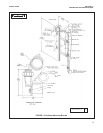
4. To check the resistance of the temperature
compensator, connect an ohmmeter to the
green and white leads of the sensor. The
resistance should be as indicated at the
temperature listed below: If the resistance
as specified above cannot be achieved,
replace the sensor (Figure 5-2).
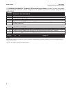
Temperature Resistance Chart
5. To check for shorted sensor leads, meas-
ure the resistance between one tempera-
ture compensator wire (green or white) and
the cathode (black) lead and anode (red)
lead. The meter should indicate an open
circuit (100 megohms or more). Repeat the
measurement using the other temperature
compensator wire. If the sensor shows a
short circuit, the sensor is defective and
should be replaced.
MODEL 430 DO SECTION 4.0
TROUBLESHOOTING
SECTION 4.0
TROUBLESHOOTING
TEMPERATURE RESISTANCE (ohms)
0°C 371.40K
10°C 214.50K
20°C 128 00K
25°C 100.00K
30°C 78.00K
40°C 49.80K
50°C 32.36K