Instruction Manual
IB-106-300NH Rev. 4.2
July 2002
1-4 Description and Specifications Rosemount Analytical Inc. A Division of Emerson Process Management
World Class 3000
9. An operator can set up, calibrate, or
troubleshoot the IFT in one of two
ways:
(a) Optional General User Interface
(GUI). The GUI is housed within
the IFT electronics enclosure and
makes use of an LCD and keypad.
(b) Optional HART Interface. The IFT's
4-20 mA output line transmits an
analog signal proportional to oxy-
gen level. The line also carries all
information normally accessed by
use of the General User Interface
LCD and keypad. This information
can be accessed through the
following:
1 Rosemount Model 275 Hand-
held Communicator - The
handheld communicator re-
quires Device Descriptor (DD)
software specific to the World
Class 3000 product. The DD
software will be supplied with
many model 275 units, but
can also be programmed into
existing units at most Fisher-
Rosemount service offices.
2 Personal Computer (PC) -
The use of a personal com-
puter requires Cornerstone
software with Module Library
(ModLib) specific to the World
Class 3000 product.
3 Selected Distributed Control
Systems - The use of distrib-
uted control systems requires
input/output (I/O) hardware
and software which permit
HART communications.
e. Handling the Oxygen Analyzer.
It is important that printed circuit
boards and integrated circuits are
handled only when adequate antistatic
precautions have been taken to pre-
vent possible equipment damage.
The oxygen analyzer is designed for
industrial application. Treat each
component of the system with care to
avoid physical damage. The probe
contains components made from ce-
ramics, which are susceptible to
shock when mishandled.
NOTE
Retain packaging in which the oxygen
analyzer arrived from the factory in
case any components are to be
shipped to another site. This packag-
ing has been designed to protect the
product.
f. System Considerations
Prior to installation of your Rosemount
World Class 3000 Oxygen Analyzer with
Intelligent Field Transmitter make sure that
you have all of the components necessary
to make the system installation. Ensure that
all the components are properly integrated
to make the system functional.
Once you have verified that you have all the
components, select mounting locations and
determine how each component will be
placed in terms of available power supply,
ambient temperatures, environmental con-
siderations, convenience, and serviceability.
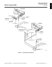
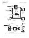
A typical system installation is illustrated in
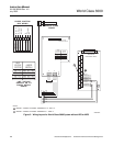
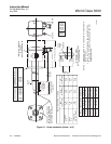
Figure 1-2. Figure 1-3 shows a typical sys-
tem wiring. For details on installing the indi-
vidual components of the system, refer to
Section 2, Installation.


