


Page 5
II. INSTALLATION
BASIC INSTALLATION
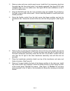
1. Before doing any service work, the unit disconnect must be turned off and locked to
prevent injury or death due to electrical shock or contact with moving parts. The
thermostat must also be turned off.
2. Unpack the ultraviolet light kit, accessories, and Installation Instructions.
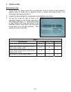
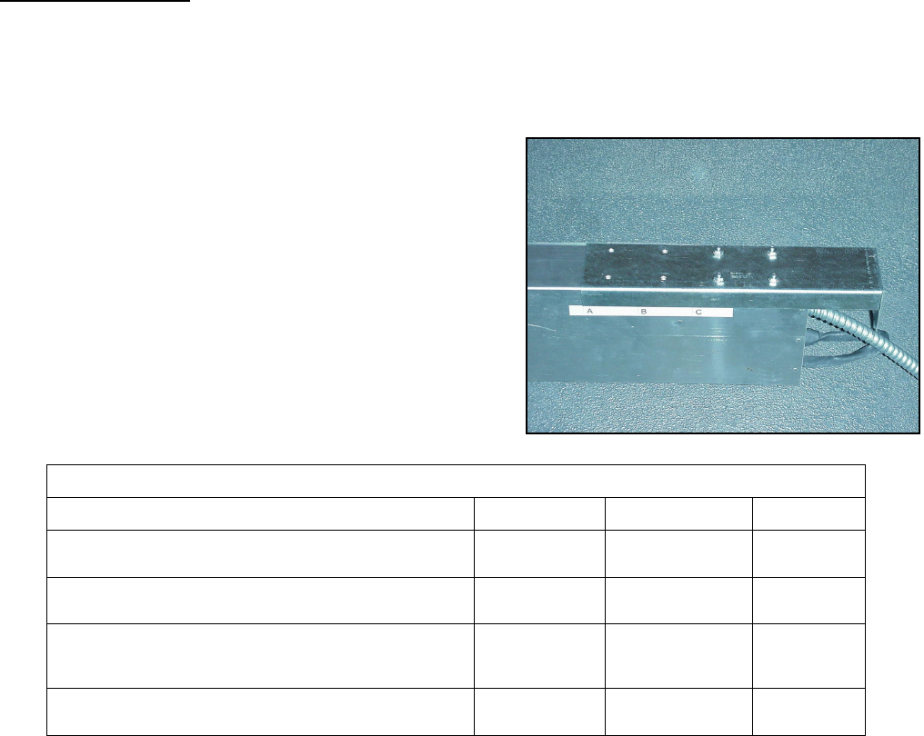
3. On the top of the UV light kit there is an
adjustable bracket on the left and right side of
the housing (see figure 1). Loosen the screws
to right bracket and move the bracket to the
specified location using Table 2 and the labels
on the back of the UV light assembly. Then
tighten the screws. Set aside.
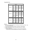
Table 2
Wall Mount Unit UV Light width Bracket Position Cabinet Size
WA182, WA242, WH183, WH242, WL182, WL242 33-7/8 A 2
WA302, WA372, WH301, WH361 WL302, WL372,
WH311, SH311,WH261, SH261
37-7/8 B 3
WA423, WA484, WH421, WH483, WL423, WL484,
WH381, WH431, WH491, SH381, SH431, SH491,
WA602, WH602, WL602
41-7/8 C 5
WA701, WA721, , WL701, WH611, SH611 41-7/8 C 6
Figure 1