70
Service
Removing and Replacing Assemblies
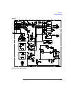
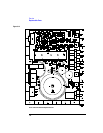
Probe Control and Power Module
Use the following procedure to disassemble the probe control and power module.
WARNING Hazardous voltages exist on the power supply. To avoid electrical shock, adhere closely
to the following procedures.
1 Remove the power cord.
2 Remove four flathead screws and remove the top cover.
WARNING Be sure to reconnect the safety ground when reassembling the instrument.
3 Unplug the safety ground from the tab on the rear panel of the instrument.
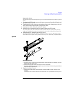
4 Note the orientation of the knobs. Remove the two knobs.
5 On the bottom of the instrument, remove the 5mm screw that fastens the
transformer support.
6 Remove the following pan-head screws.
• Three directly on the PC board.
• Two on the ac input connector.
• Two on the heatsink.
7
Remove the PC board. Slide it slightly forward so parts will clear the rear panel,
then lift the rear of the board out while sliding it backwards.
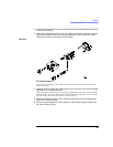
8 Remove the two heatsink spacers from the standoffs that were directly under
the heatsink.
9 Reverse the procedure to reassemble the control and power supply.


