26
Calibration Tests and Adjustment
Equipment Required
Introduction
This chapter is divided into two sections. The first section gives
calibration tests and the second adjustment procedures for the 1141A
Differential Probe and 1142A Probe Control and Power Module.
Equipment Required
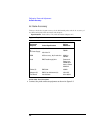
A complete list of equipment required for the calibration tests and adjustments is listed
in “Recommended Test Equipment” on page 9. Equipment required for individual
procedures is listed at the procedure. Any equipment satisfying the critical specifications
listed may be substituted for the recommended model.
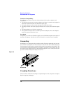
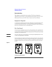
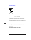
The Test Board
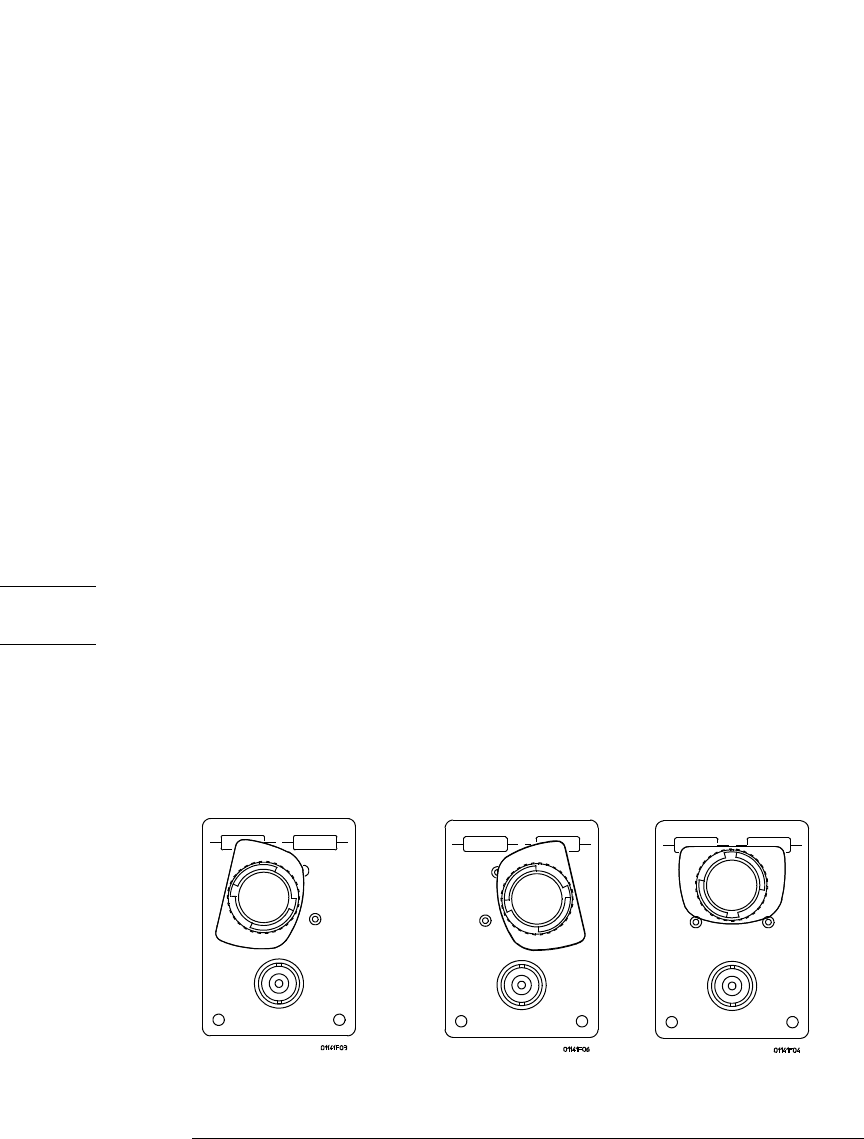
The test board is a supplied accessory for use during calibration tests and adjustments
to connect signals to the differential probe (with or without adapters). A BNC connector
connects the test board to a cable from the signal generator. The board includes a 50 Ω
termination (two 100 Ω resistors).
CAUTION The power rating of the 50 Ω termination is 1.0 W. Keep the signal input below 7 Vdc
or rms to avoid degrading the termination.
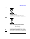
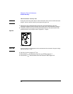
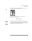
Once the probe tip caps and probe tips have been removed, the probe can be connected
to the test board in one of three ways, as shown in the figure below. At each position of
the probe, probe inputs are connected to a different combination of signal and ground.
A separate terminal on the test board connects the ground of the probe to the signal
ground.
Figure 2-1
Test Board Showing Probe Positions


