69
Service
Removing and Replacing Assemblies
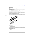
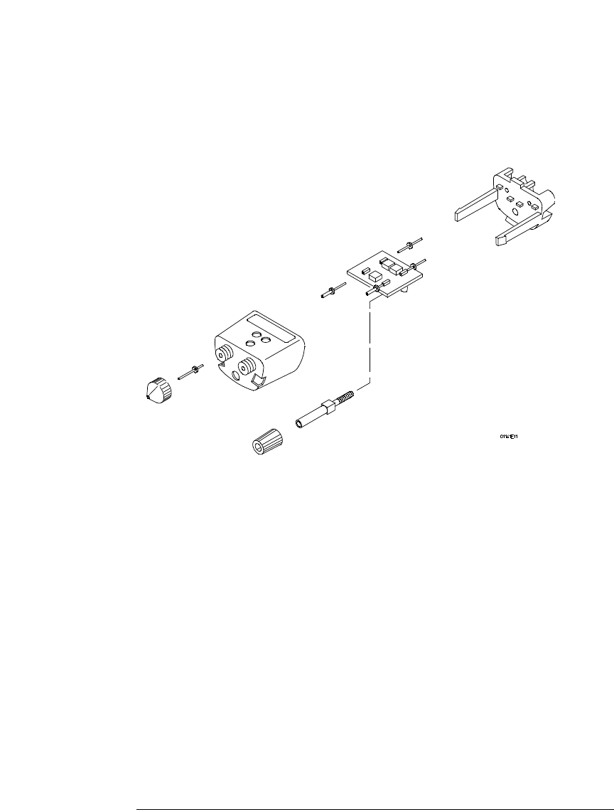
2 Combine the thumbwheel screw and thumbwheel and insert them into the hole
in the outer housing.
3 Insert the substrate/board into the outer housing. Slip the attenuator ground
(attenuator adapters only) over the thumbwheel screw and seat the input
connectors in the proper holes in the housing.
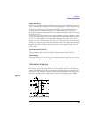
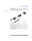
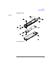
Figure 3-10
Reassembling the Adapter
Do not force reassembly of the adapter. The housing halves will slide together with
moderate friction.
4 Align the inner housing tabs with the grooves in the side of the outer housing
and slide the two partly together.
While seating the thumbwheel screw and pins, it will help to hold the assembly vertically,
with the input end of the adapter down. This will allow the assemblies to sit vertically
and more easily align with the holes in the inner housing.
5
Seat the thumbwheel screw first, then the output pins, into the appropriate
holes in the inner housing.
6 Once the two housings are nearly together, press them together firmly until
the tabs click into place.


