


CHAPTER 4
Performing Advanced Functions
38
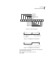
between the frames 38 and 39 is that the later accomodates for 12
bit analog values for the sensor sampling inputs and 16 bit
counters for the pulse counter inputs. In addition, the correspon-
dence between input analog and digital ports and their position in
the frame differs.
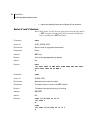
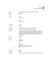
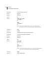
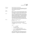
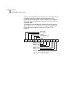
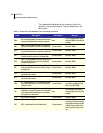
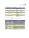
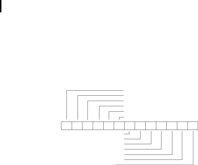
The composition of the data block of a frame type 38 (the bytes
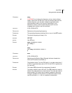
marked as d1, d2... dn) is depicted in Figure 9, a type 39 frame in
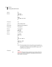
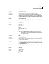
Figure 10 while the digibyte is depicted in Figure 11 and
Figure 12.
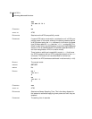
Figure 9. Frame 38 description
D1 D2 D3 D4 D5 D6 D7 D8 D9 D10 D11 D12 D13
RF incoming
RF outgoing
Digibyte
Pulse Counter I/O B
Pulse Counter I/O A
Battery
Cabling 1 I/O B
Cabling 2 I/O B
Cabling 3 I/O B
Cabling 1 I/O A
Cabling 2 I/O A
Cabling 3 I/O A
Reserved