Chapter 2 Installation
2-23
2.9 Interface Cable
2.9.1 Connecting the Interface Cable
Turn off the printer, and connect an appropriate interface cable to the correct
connector on the rear of the printer.
Turning the printer on
The top line of the LCD display reads:
Loading
followed by asterisks progressing across the bottom line:
**************
Following an LED self test, asterisks progress across both lines of the display
**************
**************
and the Power On Self Test ends with the top line of the display reading:
Ready
Note: While turned on, the printer will go into the standby state if it remains idle
for a period of time. If an error message appears, see “Functions of LCD and
Lamps” on page 4-2.
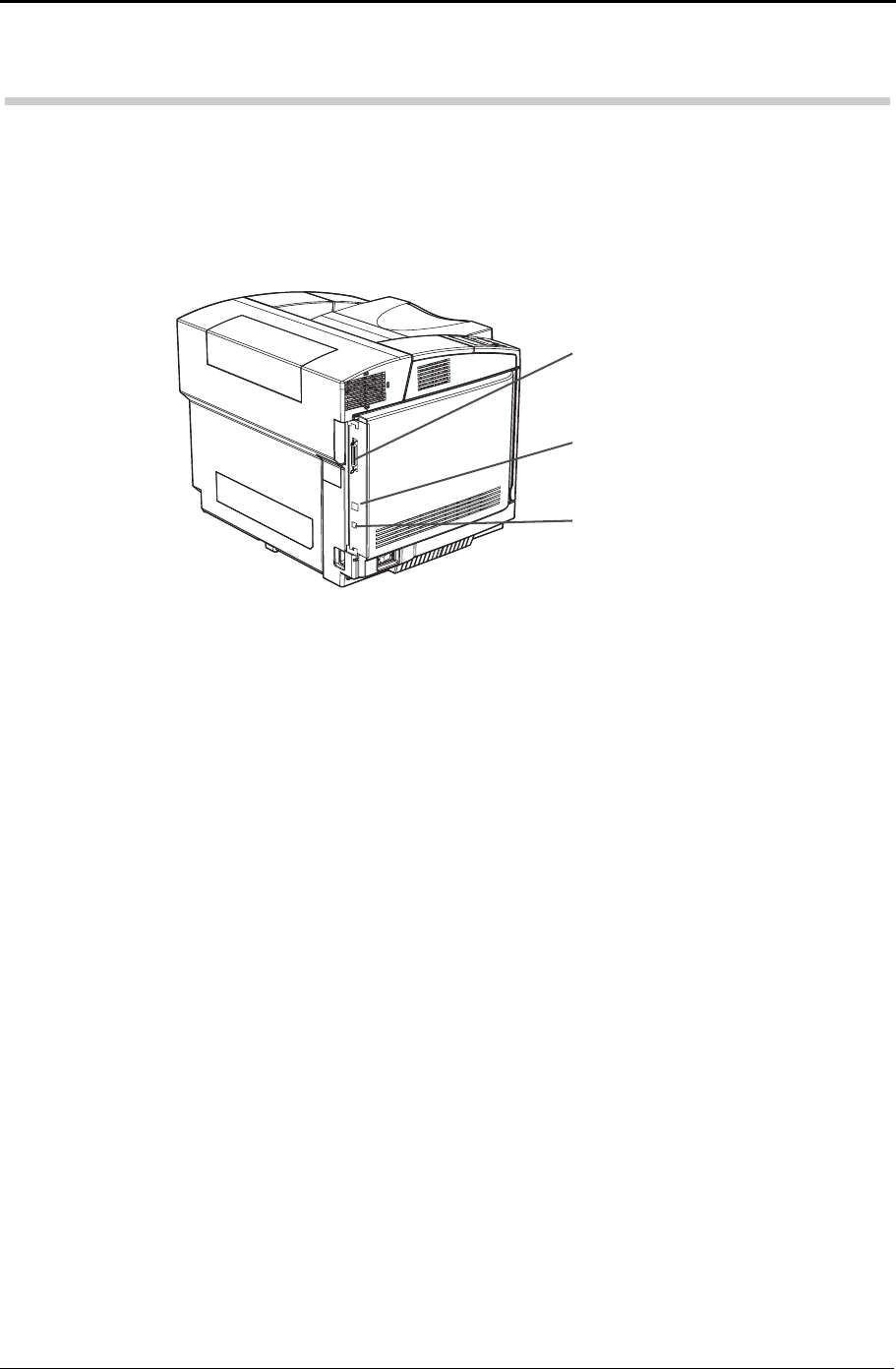
Parallel interface connector
This connector is used for parallel con-
nection of the printer.
LAN interface connector
This connector is used for 10BASE-Tor
100BASE-TX LAN connection of
the printer.
USB interface connector
This connector is used for USB cable
connection of the printer.


