XTRA Series • Installation
Installation, cont’d
2-4
XTRA Series • Installation
2-5
1. Elevated operating ambient temperature — If installed
in a closed or multi-unit rack assembly, the operating
ambient temperature of the rack environment may be
greater than room ambient temperature. Therefore, install
the equipment in an environment compatible with the
maximum ambient temperature (Tma = +122 °F, +50 °C)
specied by Extron.
2. Reduced air flow — Install the equipment in a rack so that
the amount of air flow required for safe operation of the
equipment is not compromised.
3. Mechanical loading — Mount the equipment in the rack
so that a hazardous condition is not achieved due to
uneven mechanical loading.
4. Circuit overloading — Connect the equipment to
the supply circuit and consider the effect that circuit
overloading might have on overcurrent protection and
supply wiring. Appropriate consideration of equipment
nameplate ratings should be used when addressing this
concern.
5. Reliable earthing (grounding) — Maintain reliable
grounding of rack-mounted equipment. Pay particular
attention to supply connections other than direct
connections to the branch circuit (e.g. use of power strips).
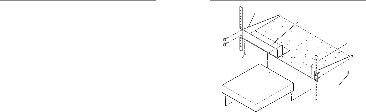
Rack mounting
The XPA 1002 or XPA 2001 can be mounted in a rack shelf using
the optional RSU 129 1U Universal rack shelf (Extron part
#60-190-01) or the 1U Basic rack shelf (Extron part #60-604-01),
as follows.
1. If feet were installed on the bottom of the amplifier,
remove them.
2. Place the amplifier on one half of the rack shelf. Align the
front of the amplifier with the front of the shelf, and align
the threaded holes on the bottom of the amplifier with the
holes in the rack shelf.
3. Attach the amplifier to the rack shelf with the two
provided 4-40 x 3/16” machine screws. Insert the screws
from the underside of the shelf, and securely fasten them
into diagonally-opposite corners.
See the following illustration.
Use 2 mounting holes on
opposite corners.
(2) 4-40 x 3/16"
Screws
NOTE: Using screws longer
than 3/16” will damage the
unit and void the warranty.
1U Universal Rack Shelf
Front false
faceplate
uses 2
screws.
1/2 Rack Width Front False
Faceplate
Rack mounting of the amplifier
4. Attach the false front panel (provided with rack shelf part
#60-190-01) to the unoccupied side of the rack (as shown
above), or install a second half-rack-width device in that
side by repeating steps 1 through 3.
5. Attach the rack shelf to the rack using four 10-32 x ¾" bolts
(provided). Insert the bolts through #10 beveled washers,
then through the holes in the rack, as shown above.
Rack mounting ventilation recommendations
Excessive heat can decrease the optimal lifetime of the power
amplifier. An over temp indicator LED on the front panel of
the amplifier lights red whenever the recommended ambient
temperature has been exceeded (see "Front Panel Features and
Operation" in chapter 3).
To reduce the chances for an over temp condition, the XPA(s)
should be arranged in a rack environment so that adequate
airow is available both above and below the XPA whenever
possible. No more than two XPAs should be arranged one-
on-top-of-the-other in a rack without an open space between
them, as shown in the following illustration. An XPA can also
be arranged above or below another non-XPA device, but there
must be an open space both above and below those devices.


