XTRA Series • Installation
Installation, cont’d
2-8
XTRA Series • Installation
2-9
100-240V 1.3A, 50-60Hz
VOL/MUTE
10V
STANDBY
CLASS 2 WIRING
1
2
LISTED 17TT
AUDIO/VIDEO
APPARATUS
CLASS 2 WIRING
XPA 1002
C
US
LEVEL
1
1 2
12
LIMITER/
PROTECT
SIGNAL
2
INPUTS
OUTPUT
REMOTE
0
0
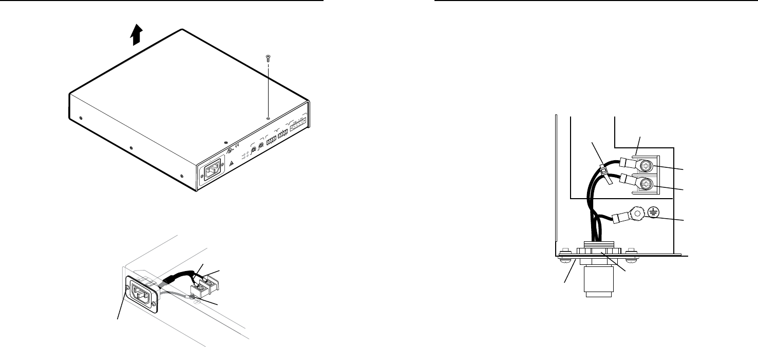
Remove (8)
screws
Lift Cover Straight Up
3. Remove the 2 screws holding the hot (line) and neutral
wires from the terminal block on the PCB.
100-240V 1.3A
50-60Hz
Remove screws
(both sides) to release
IEC connector plate.
Remove nut
Blue Wire
Brown Wire
L
N
4. Remove the ground wire nut from the grounding stud on
the bottom of the enclosure, as shown above.
5. Remove the 2 screws from the IEC plate, and remove the
IEC connector plate and the attached wires through the
rear panel of the XPA, as shown above.
6. Thread the 18-gauge power wires through the length of the
electrical conduit tube.
7. Install the EMT adapter plate with conduit attached into
the opening from which the IEC connector was removed.
in step 5.
8. Slide the conduit nut over the bundle of wires exiting the
conduit and onto the conduit itself. Hand tighten the
conduit nut to the conduit.
9. Attach the EMT adapter plate assembly to the XPA using
the 2 screws that were removed in step 5.
10
. Connect the black hot (line) and white neutral wires to
the terminal block on the PCB using the 2 screws that
were removed in step . Use the included zip tie wrap to
secure the two wires together close to the terminals. See
the following illustration.
W
Ensure that you observe correct wire polarity. The
following illustration shows the location of the hot
(L) and neutral (N) terminals.
LINE
NEUTRAL
L
N
Conduit Nut
EMT Adapter Plate
Terminal Block
Zip-Tie
Ground
Wire Nut
Hot
Terminal (Black)
Neutral
Terminal (White)
11. Connect the ground wire, as shown above, to the
grounding stud on the bottom of the enclosure using the
nut that was removed in step 4.
12. Replace the cover of the XPA by attaching the 8 screws that
were removed in step 2.


