XTRA Series • Operation
Operation, cont’d
3-6
XTRA Series • Operation
3-7
N
On the XPA 2001, the single control adjusts the levels
of both channels simultaneously prior to summing them
together.
To adjust the XPA amplier's input level, do the following:
1
. If connecting to a source device with a volume control
(variable output), ensure that the volume on the source
device is set to its lowest point, then adjust the level(s) of
the XPA fully counterclockwise.
2. Set the source device's volume to its maximum volume
level. No sound should come out.
3. Return to the XPA amplier and raise the level(s) until
sound distortion occurs, then lower the level(s) slightly
until any distortion disappears. This setting ensures that,
whatever the source device volume setting may be, no
clipping occurs.
N
When setting volume control through a source device,
ensure that the device's volume is set to variable out.
Consult the device's user manual for detailed instructions
on its calibration.
à
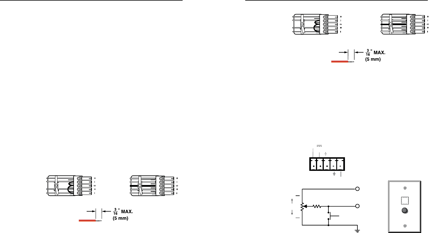
Balanced or unbalanced stereo audio input connector — Wire
the 3.5 mm 5-pin captive screw connector for balanced or
unbalanced input.
Unbalanced Stereo Input
Balanced Stereo Input
Do not tin the wires!
Tip
Ring
Tip
Ring
L R
Sleeves
Tip
Sleeve
Sleeve
Tip
L R
N
The XPA 1002's output power can be effectively doubled
by using only one input channel and bridging the output.
The XPA 1002 will output 200 watts @ 8 ohms or 120
watts @ 16 ohms in bridged mode.
See "Bridged mono output" in this chapter for wiring
instructions when bridging the XPA 1002.
â
Balanced or unbalanced mono audio input connector — Wire
the 3.5 mm 5-pin captive screw connector for balanced or
unbalanced input.
Balanced Mono InputUnbalanced Mono Input
(high impedance)
Do not tin the wires!
Tip
Ring
Tip
Ring
L R
Sleeves
Tip
Sleeve
Sleeve
Tip
L R
f
Remote control connector — The 3.5 mm 5-pin captive screw
receptacle is used to remotely control two functions through
contact closure: See the following circuit diagram.
• Pins 1, 2, and 3 control volume by varying the DC voltage
from 0 V (full attenuation) to 10 V (maximum volume) with
full muting in effect when pin 2 is connected to ground (pin3).
Use the included 3-pin captive screw connector. See "Remote
volume control" in this chapter.
MUTE
VOLUME
GND
10K OHMS
2K OHMS
MAX
2 VOL/MUTE
3
1 10 V
MIN
123
STANDBY
MUTE SWITCH
VOL/MUTE
10V 50 mA


