


32 www.xilinx.com SPI-4.2 v8.5 Getting Started Guide
UG154 March 24, 2008
Chapter 4: Detailed Example Design
R
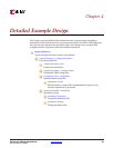
If the core was generated with the Full System Hardware Evaluation or the Full license, the
implementation script is present and performs the following steps:
1. Synthesizes the example design using the selected synthesis tool (XST or Synplify).
2. Runs ngdbuild to consolidate the core netlists, wrapper netlist, and constraints file
into the common database.
3. Runs map to perform technology specific mapping of the design.
4. Runs par to perform place and route of the design.
5. Runs trce to perform static timing analysis of the routed design.
6. Runs bitgen to generate a bitstream for download to the target FPGA.
7. Runs netgen to generate a post-par simulation model for use in timing simulation.
Simulation Script Details
The simulation scripts for ModelSim and NCSIM that simulate the demonstration test
bench are located in one of the following directories:
<proj_dir>/<component_name>/simulation/{functional | timing }/
For functional simulation, the simulation script performs the following tasks:
1. Compiles the simulation models provided with the core.
2. Compiles the loopback example design.
3. Compiles the wrapper file, which instantiates the cores and the loopback.
4. Compiles the demonstration test bench.
5. Starts a simulation of the demonstration test bench.
6. Opens the waveform viewer and adds key signals
(wave_mti.do|wave_ncsim.sv).
7. Runs the simulation.
For timing simulation, the simulation script performs the following tasks:
1. Compiles the post-par design example, which includes the cores and the loopback.
2. Compiles the demonstration test bench.
3. Starts a simulation of the demonstration test bench.
4. Opens the waveform viewer and adds key signals
(wave_mti.do|wave_ncsim.sv).
5. Runs the simulation.
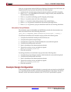
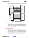
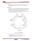
Example Design Configuration
In the example design, a Loopback Module is connected to the user interface of the SPI-4.2
core. Typically, the user interface would be connected directly to the design. The SPI-4.2
Interface, which is the interface defined by the OIF-SPI4-02.1 specification, typically