


2
Please Do Not Return This Product To The Store. Contact your local Wayne-Dalton dealer. To find your local Wayne-Dalton dealer,
refer to your local yellow pages business listings or go to the Find a Dealer section online at www.Wayne-Dalton.com
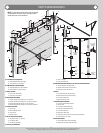
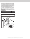
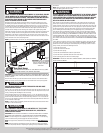
A. FLAG ANGLES (AS REQUIRED):
A1. Fully Adjustable (F.A.) Flag Angles
A2. Quick Install (Q.I.) Flag Angles
B. JAMB BRACKETS (AS REQUIRED):
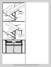
B1. Fully Adjustable (F.A.) Jamb Brackets
B2. Quick Install (Q.I.) Jamb Brackets
C. TRACK ROLLERS:
C1. Short Stem Track Rollers
C2. Long Stem Track Rollers
D. GRADUATED END HINGES:
D1. Single Graduated End Hinges (S.E.H.), Anti-Pinch
D2. Single Graduated End Hinges (S.E.H.), Industry Standard
D3. Double Graduated End Hinges (D.E.H.), Anti-Pinch
D4. Double Graduated End Hinges (D.E.H.), Industry Standard
E. STACKED SECTIONS:
E1. Top Section
E2. Intermediate(s) Section
E3. Lock Section
E4. Bottom Section
F. TOP FIXTURES (AS REQUIRED):
F1. Top Fixture Bases - (L-Shaped)
F2. Top Fixture Slides
F3. Top Fixture Assemblies
G. STRUT(S) (AS REQUIRED):
G1. Strut (U-shaped)
G2. Strut (A-symmetrical)
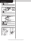
H. DRAWBAR OPERATOR BRACKET (FOR TROLLEY OPERATED DOORS):
H1. Top Half Drawbar Operator Bracket
H2. Bottom Half Drawbar Operator Bracket
H3. Drawbar Operator Bracket Arm
I. TRACKS:
I1. Left Hand Horizontal Track Assembly
I2. Right Hand Horizontal Track Assembly
I3. Left Hand Vertical Track
I4. Right Hand Vertical Track
J. TORSION SPRING ASSEMBLY:
J1. Center Bracket Bushing Assembly
J2. Torsion Shaft
J3. Left Hand End Bearing Bracket
J4. Right Hand End Bearing Bracket
J5. Left Hand Cable Drum
J6. Right Hand Cable Drum
J7. Right Hand and Left Hand Torsion Springs (As Required)
J8. Counterbalance Lift Cables
K. REAR BACK HANGS:
K1. Left Hand Rear Back Hang Assemblies
K2. Right Hand Rear Back Hang Assemblies
A2.
A2.
A1.
B2.
B1.
B2.
B1.
A1.
C1.
C2.
D1.
D3.
D4.
E4.
E1.
E2.
E3.
G1.
G2.
I4.
I2.
I1.
I3.
K2.
K1.
J4.
J3.
J8.
J7.
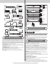
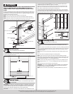
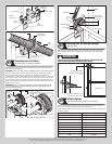
Lower hole
of hole/
slot pattern
3rd
hole set
Top of vertical
track
B1. (Fully
Adjustable
Feature)
2nd
hole set
1st
hole set
B2. (Quick
Install
Feature)
3rd hole
set
Top of vertical
track
2nd
hole set
1st hole
set
Middle
hole
Bottom
hole
Top
hole
D2.
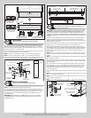
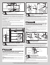
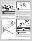
NOTE: The illustrations shown on this page are general
representations of the door parts. Each specific door
models may have unique variations.
J5.
J1.
J8.
J7.
J2.
J6.
H1.
H2.
H3.
C1.
F1.
F2.
C1.
F1.
F2.
F3.
F3.
PARTS BREAKDOWN