


Please Do Not Return This Product To The Store. Contact your local Wayne-Dalton dealer. To find your local Wayne-Dalton dealer,
refer to your local yellow pages business listings or go to the Find a Dealer section online at www.Wayne-Dalton.com
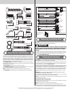
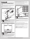
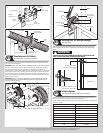
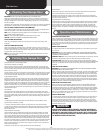
Center bracket
bushing
Stationary
spring cone
Center bracket
Torsion
spring
Stationary
spring cone
Torsion spring
Spring
warning tags
Center bracket
bushing assembly
Stationary spring cone
(2) 3/8”-16 x 1-1/2”
Hex head bolts
(2) 3/8”-16 Nuts
Torsion
spring
Torsion
spring
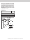
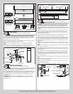
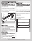
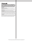
Counterbalance Lift Cables
Tools: Step Ladder, Locking Pliers, 3/8” Wrench
23
Starting on the left hand side, thread the counterbalance lift cable up and around the front
side of the left hand cable drum.
IMPORTANT: VERIFY THAT THERE ARE NO COUNTERBALANCE LIFT CABLE OBSTRUCTIONS.
Hook the counterbalance lift cable into the left hand cable drum. Slide the left hand cable
drum up against the left hand end bearing bracket. Counterbalance lift cable should
terminate at the 3 o’clock position. Tighten the (2) set screws in the drum to 14-15 ft. lbs. of
torque (once set screws contact the shaft, tighten screws one full turn). Rotate the left hand
drum and torsion shaft until counterbalance lift cable is taut. Now attach locking pliers to the
torsion shaft and brace locking pliers up against jamb to keep counterbalance lift cable taut.
Repeat for right hand side.
IMPORTANT: INSPECT EACH COUNTERBALANCE LIFT CABLES MAKING SURE THEY ARE
SEATED PROPERLY ONTO THE CABLE DRUMS AND THAT BOTH COUNTERBALANCE LIFT
CABLES HAVE EQUAL TENSION.
Left hand
cable drum
Counterbalance lift cable hooked in cable
drum
Counterbalance
lift cable
Torsion
shaft
Left hand
end bearing
bracket
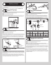
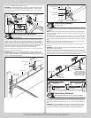
Left hand cable
drum
Counterbalance lift
cable
Locking pliers
Set screws
JambJamb
Left hand end
bearing bracket
Torsion shaft
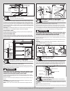
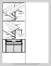
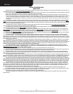
Securing Door for Spring Winding(s)
Tools: Vice Clamps
24
With the door in the fully closed position, place vice clamps onto both vertical tracks just
above the third track roller. This is to prevent the garage door from rising while winding
springs.
WARNING WARNING
FAILURE TO PLACE VICE CLAMPS ONTO VERTICAL TRACK CAN ALLOW
DOOR TO RAISE AND CAUSE SEVERE OR FATAL INJURY.
Vice clamps above third
track roller on both sides of
door
Bottom section
Vice clamps attached to inner
and outer rail of vertical track
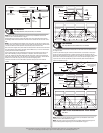
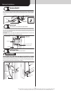
Winding Springs
Tools: Step Ladder, Approved winding bars, 3/8” Wrench
25
Position a ladder slightly to the side of the spring so that the winding cone is easily acces-
sible, and so your body is not directly in line with the winding bars.
Check the label attached to the spring warning tag for the required number of complete turns
to balance your door.
Door Height Approximate Spring Turns
6’0” 6-7/8 Turns
6’3” 7-1/8 Turns
6’5” 7-1/4
6’6” 7-3/8 Turns
6’8” 7-1/2
6’9” 7-5/8 Turns
7’0” 7-7/8 Turns
7’3” 8 Turns
7’6” 8-1/4 Turns
12