


UV CROSSLINKERS UVP
C. Operations With The Internal Chassis Assembly Removed
Removal of the assembly
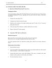
1. Release the wire to the micro switch located on the bottom left internal chassis assembly.
2. Release the main power cable to ballasts - black wire with connector (color red).
3. Release all eight nuts positioned four on top of the unit, two sets on either side of the unit.
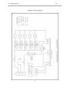
See diagram for positions.
4. Slide unit out from the main frame.
Replacement of reflector
The reflector is located inside of the internal chassis assembly.
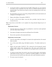
1. Release the eight screws-four on the top and two on either side of the unit.
2. Pull the reflector out towards the front of the unit. Note: for cleaning the reflector, refer to
Section 6 for maintenance/care/cleaning of the crosslinker.
3. For replacement-reverse the above procedure.
D. Operations With The Reflector Removed
Replacement of ballasts
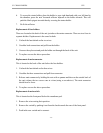
The ballasts are fitted to the right hand side of the internal chassis assembly.
1. Select the ballast(s) which need to be replaced.
2. Cut the tie wraps to locate the ballast electrical connectors.
3. Cut these wires and mark positions.
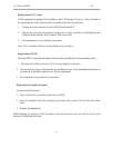
4. Re-fit new ballasts using M4 posidrive screws with shake proof and plain washers with a
nut as fitted on the diagram.
- 17 -