


Oxygen Analyzer
Teledyne Analytical Instruments ix
List of Figures
Figure 1-1: BDS-3960 Front Panel ................................................ 15
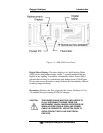
Figure 1-2: Model BDS 3960 Rear Panel ...................................... 17
Figure 2.1: Cross Section of the BDS Oxygen Sensor ................. 20
Figure 2.2: BDS sensor output at different gas flow rate ............... 21
Figure 2-3: A simplified BDS Sample System ............................... 22
Figure 2.4 Typical Purge-down Curve After Air Saturation............ 23
Figure 2.5: Adding DI Water to the BDS Sensor .......................... 24
Figure 2-6: Flow Diagram.............................................................. 26
Figure 2-7: BDS 3960 Electronics Block Diagram .........................28
Figure 3-1: Model BDS 3960 Front Panel ..................................... 31
Figure 3-2: Required Assembly Drawer Clearance ....................... 31
Figure 3-3: Rear Panel of the Model BDS 3960 ........................... 32
Figure 3-4: Equipment Interface Connector Pin Arrangement....... 34
Figure 3-5: Adding Electrolyte to the BDS Sensor....................... 40
Figure 4-1: Main Menu .................................................................. 43
Figure 4.2: Parameter Selection Box............................................. 46
Figure 4.3: Range Options List Box............................................... 54
Figure 4.4: Range Setup Screen................................................... 54
Figure 5.1 Adding Water into the BDS sensor............................... 59
Figure 5-2: Removing Fuse Block from Housing........................... 60