Introduction BDS 3960
Teledyne Analytical Instruments 16
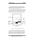
Access Drawer: For access t o the BDS S ensor And pr essur e regul ator.
T he f ront panel sli des out when the four thumb screws ar e loosened.
Openi ng the int er ior gives access to most ci rcui t boards t oo.
1.5 Rear Panel (Equipment Interface)
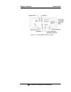
The rear panel, shown in Figure 1-2, contains the gas and electrical
connectors for external inlets and outlets. The connectors are described
briefly here and in detail in Chapter 3 Installation. Except for gas, AC
power, and RS-232 communications I/O, all user connections for analog
output, alarms, calibration and remote probe contacts are available
through the 50 pin equipment interface connector. User connections
made at the rear panel include:
• Power Connection 110 VAC power source (220 VAC
optional.
• Gas Inlet and Outlet One inlet and one exhaust out.
• Moisture By-pass Additional vent line for condensate
• Analog Outputs 0–1 VDC oxygen concentr ation plus
0-1 VDC r ange I D, and isolated
4–20 mA DC oxygen concentr ation
plus 4-20 mA DC range ID.
• Alarm Connections 2 concentration alarms and 1
system alarm.
• Remote Probe Used in the BDS 3960 for
controlling external solenoid
valves only.
• Remote Span/Zero Digital inputs allow external
control of analyzer calibration.
• Calibration Contact To notify external equipment that
instrument is being calibrated and
readings are not monitoring
sample.•
Range ID Contacts Four separate, dedicated, range
relay contacts. Low, Medium,
High, Cal.


