


Installation BDS 3960
Teledyne Analytical Instruments 32
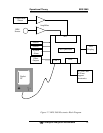
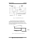
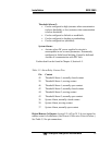
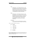
3.3 Rear Panel Connections
Figure 3-3 shows the Model BDS 3960 rear panel. There are ports
for gas inlet and outlet, power, communication, and analog
concentration output.
Figure 3-3: Rear Panel of the Model BDS 3960
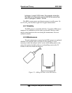
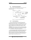
3.3.1 Gas Connections
T h e un i t is ma nu f a ct u r e d wi t h
1/ 4 in ch VC R f i t t i ngs wi t h t he
ex ce pt i on of i ns t r um e nt ai r fi t t i ng . Al l of th e gas conn ec t i o ns ar e
l o ca t e d on the r ea r of the ana l yz er . F or al l VC R f i t t i ngs , ins er t a gas ket
( T AI P N G2 84) bet wee n the f i t t i n gs an d ti ght en th e fe m al e and m al e
nu t s unt i l fi n ge r t i gh t ; th en by hol di n g th e m al e nut wi t h a wr e nc h,
t i gh t e n t he fe m a l e nu t wi t h a sec on d wr e nc h an add i t i o nal 1/ 6 tu r n .
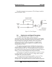
SAMPLE IN: The gas of interest connections are made at the
SAMPLE
IN
and EXHAUST OUT connections. For zero calibration, the sample gas
is rerouted through an oxygen scrubber to supply oxygen-free zero cal
gas. A VCR fitting is provided for the inlet connection.
The inlet gas pressure should be regulated to pressures between 5 to
50 psig so that the internal regulator can be adjusted to maintain a flow
between 0.5 to 1.0 SLPM. If pressure is too low, the flow will drop
below 0.5 SLPM which is below the threshold to which the sensor is
sensitive (see Section 2.2.2). If pressure is too high, it will force gas into
the electrolyte and cause damage to the sensor. The internal pressure
regulator is helpful if the sample pressure varies.