Trace Oxygen Analyzer Maintenance 5
5-1
Teledyne Analytical Instruments
Maintenance
5.1 Routine Maintenance
Aside from normal cleaning and checking for leaks at the gas connec-
tions, routine maintenance is limited to replacing Micro-Fuel cells and fuses,
and recalibration. For recalibration, see Section 4.4 The Zero and Span
Functions.
WARNING: SEE WARNINGS ON TITLE PAGE OF THIS MANUAL.
5.2 Major Internal Components
All internal components are accessed by unbolting and swinging open
the front cover, as described earlier. The major internal component locations
are shown in Figure 3-1, the cell block is illustrated in Figure 3-2, and the
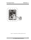
fuse receptacle is shown in Figure 3-3
The 3020T contains the following major internal components:
• Micro-Fuel Cell (L-2C)
• Stainless steel cell block
• Customer Interface PCB (Power Supply on bottom surface)
• Preamp PCB (Contains Microprocessor)
• Front Panel PCB (Contains Displays)
5 digit LED meter
2 line, 20 character, alphanumeric, VFD display
• Solenoid Operated Gas Control Valves (–C option only).
See the drawings in the Drawings section in back of this manual
for details.


