


3 Installation Model 3020T
3-6
Teledyne Analytical Instruments
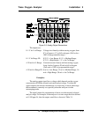
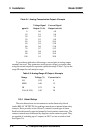
Table 3-1: Analog Concentration Output—Example
Voltage Signal Current Signal
ppm O
2
Output (V dc) Output (mA dc)
0 0.0 4.0
10 0.1 5.6
20 0.2 7.2
30 0.3 8.8
40 0.4 10.4
50 0.5 12.0
60 0.6 13.6
70 0.7 15.2
80 0.8 16.8
90 0.9 18.4
100 1.0 20.0
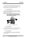
To provide an indication of the range, a second pair of analog output
terminals are used. They generate a steady preset voltage (or current when
using the current outputs) to represent a particular range. Table 3-2 gives the
range ID output for each analysis range.
Table 3-2: Analog Range ID Output—Example
Range Voltage (V) Current (mA)
LO 0.25 8
MED 0.50 12
HI 0.75 16
CAL (0-25%) 1.00 20
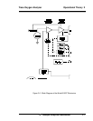
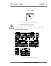
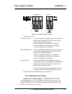
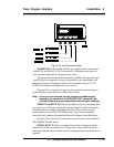
3.3.4 Alarm Relays
There are three alarm-circuit connectors on the alarm relays block
(under RELAY OUTPUTS) for making connections to internal alarm relay
contacts. Each provides a set of Form C contacts for each type of alarm.
Each has both normally open and normally closed contact connections. The
contact connections are indicated by diagrams on the connector panel. They
are capable of switching up to 3 amperes at 250 V ac into a resistive load.
See Figure 3-6.