


Trace Oxygen Analyzer Installation 3
3-9
Teledyne Analytical Instruments
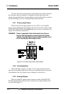
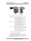
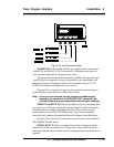
Note: The remote probe connections (paragraph 3.3.9) provide
signals to ensure that the zero and span gas valves will be
controlled synchronously. If you have the –C Internal valve
option—which includes additional zero and span gas inputs—
the 3020T automatically regulates the zero, span and sample
gas flow.
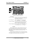
3.3.6 Range ID Relays
There are four dedicated RANGE ID CONTACT relays. The first
three ranges are assigned to relays in ascending order—Low range is as-
signed to RANGE 1 ID, Medium range is assigned to RANGE 2 ID, and
High range is assigned to RANGE 3 ID. RANGE 4 ID is reserved for the
Air Cal Range (25%).
3.3.7 Network I/O
A serial digital input/output for local network protocol. At this printing,
this port is not yet functional. It is to be used in future versions of the instru-
ment.
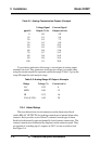
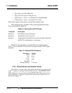
3.3.8 RS-232 Port
The digital signal output is a standard RS-232 serial communications
port used to connect the analyzer to a computer, terminal, or other digital
device. The pinouts are listed in Table 3-3.
Table 3-3: RS-232 Signals
RS-232 Sig RS-232 Pin Purpose
DCD 1 Data Carrier Detect
RD 2 Received Data
TD 3 Transmitted Data
DTR 4 Data Terminal Ready
COM 5 Common
DSR 6 Data Set Ready
RTS 7 Request to Send
CTS 8 Clear to Send
RI 9 Ring Indicator
The data sent is status information, in digital form, updated every two
seconds. Status is reported in the following order:
• The concentration in ppm or percent