


iv
Model 3020T
Teledyne Analytical Instruments
Table of Contents
1 Introduction
1.1 Overview ........................................................................ 1-1
1.2 Typical Applications ....................................................... 1-1
1.3 Main Features of the Analyzer ....................................... 1-1
1.4 Model Designations ....................................................... 1-2
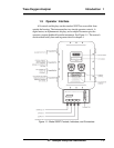
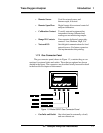
1.5 Operator Interface .......................................................... 1-3
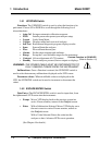
1.5.1 UP/DOWN Switch.................................................. 1-4
1.5.2 ESCAPE/ENTER Switch....................................... 1-4
1.5.3 Displays ................................................................. 1-5
1.6 Recognizing Difference Between LCD & VFD ............... 1-5
1.7 Rear Panel Equipment Interface .................................... 1-5
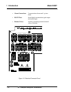
1.7.1 Electrical Connector Panel .................................... 1-5
1.7.2 Gas Connector Panel ............................................. 1-7
2 Operational Theory
2.1 Introduction .................................................................... 2-1
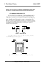
2.2 Micro-Fuel Cell Sensor .................................................. 2-1
2.2.1 Principles of Operation ............................................ 2-1
2.2.2 Anatomy of a Micro-Fuel Cell .................................. 2-2
2.2.3 Electrochemical Reactions ...................................... 2-3
2.2.4 The Effect of Pressure.............................................. 2-4
2.2.5 Calibration Characteristics ...................................... 2-4
2.3 Sample System .............................................................. 2-5
2.4 Electronics and Signal Processing ................................ 2-6
2.5 Temperature Control ...................................................... 2-8
3 Installation
3.1 Unpacking the Analyzer................................................. 3-1
3.2 Mounting the Analyzer ................................................... 3-1
3.3 Electrical Connections ................................................... 3-3
3.3.1 Primary Input Power............................................... 3-4
3.3.2 Fuse Installation..................................................... 3-4
3.3.3 Analog Outputs ...................................................... 3-4
3.3.4 Alarm Relays ......................................................... 3-6
3.3.5 Digital Remote Cal Inputs ...................................... 3-7
3.3.6 Range ID Relays ................................................... 3-9
3.3.7 Network I/O ............................................................ 3-9
3.3.8 RS-232 Port ........................................................... 3-9
3.3.9 Remote Sensor and Solenoid Valves ....................3-10
3.4 Installing the Micro-Fuel Cell ........................................ 3-11