4 Operation Model 3000TA-XL-EU
4-22
Teledyne Analytical Instruments
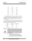
0 0.0 4.0
10 0.1 5.6
20 0.2 7.2
30 0.3 8.8
40 0.4 10.4
50 0.5 12.0
60 0.6 13.6
70 0.7 15.2
80 0.8 16.8
90 0.9 18.4
100 1.0 20.0
The analog output signal has a voltage which depends on the oxygen
concentration AND the currently activated analysis range. To relate the
signal output to the actual concentration, it is necessary to know what range
the instrument is currently on, especially when the analyzer is in the
autoranging mode.
To provide an indication of the range, a second pair of analog output
terminals are used. They generate a steady preset voltage (or current when
using the current outputs) to represent a particular range. The following table
gives the range ID output for each analysis range:
Range Voltage (V) Current (mA)
LO 0.25 8
MED 0.50 12
HI 0.75 16
CAL (0-25%) 1.00 20
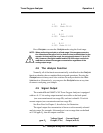
IMPORTANT: In the event of loss of flow through the analyzer, if the vent
is vented to a location of high oxygen content, oxygen will
back diffuse through the vent line and in most cases quickly
saturate the cell with oxygen which can then require a quite
long purge down time for the sensor when then exposed to
low oxygen concentrations. In the event that flow is to be
interrupted into the analyzer, it is suggested that the user do
one of the following:
1. Bag the sensor in nitrogen during this time
2. Install a shut off valve on the vent port of the ana-
lyzer or somewhere within the users sample system.


