


2-6
2 Operational Theory Model 3000TA-XL-EU
Teledyne Analytical Instruments
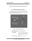
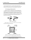
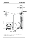
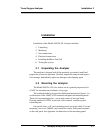
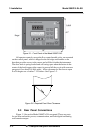
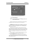
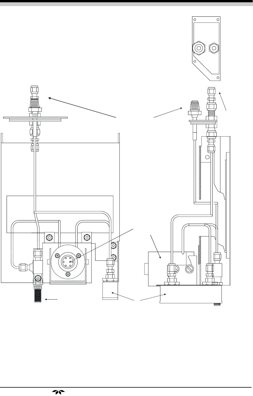
Figure 2-4: Piping Layout
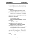
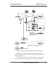
Figure 2-5 is the flow diagram for the sampling system. In the standard
instrument, calibration gases can be connected directly to the Sample In port
by teeing to the port with appropriate valves.
VCR
Sample In
TOP
RIGHT SID
E
Exhaust
Out
Cell
Block
Flowmeter
Needle Valve
EXHAUST
SAMPLE IN