Service Information
10
P6131 Instruction Manual
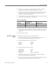
6. Remove the coax cable from the test setup. Connect the P6131 probe output
to the same vertical input on the oscilloscope.
7. Connect the probe tip through the probe-tip-to-BNC adapter to the standard
amplitude output of the calibration generator. (You must remove the light
gray probe-body shell before inserting the probe tip into the probe-tip-to-
BNC adapter.)
8. Set the calibration generator output amplitude to 0.5 V and fine tune the
amplitude to produce a precise 5-division display on the oscilloscope.
9. The deflection error indicated by the calibration generator must be within
0.75% of the error noted in step 5 above (probe attenuation accuracy of ±1%
minus the generator uncertainty). Example: if the error noted in step 5 is
+1%, the calibration generator display must now indicate between 0.25%
and 1.75%.
NOTE. You can also check the probe attenuation accuracy with an ohmmeter
having a 10 MW range and ±0.05% or greater accuracy.
An attenuation accuracy of ±1.0% is assured if the oscilloscope input resistance
is 1 MW ±0.55% (±0.5% tolerance plus 0.05% reading uncertainty) and the
probe-tip-to-output series resistance is indicated to be 9 MW ±0.35% (±1.0%
attenuation accuracy minus ±0.6% input resistance uncertainty minus ±0.05%
reading uncertainty).
10. Disconnect the test setup.
Adjustment Procedure
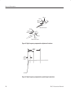
This section contains procedures to adjust the P6131 probe low-frequency and
high-frequency compensations. Always perform the low-frequency compensation
adjustment before proceeding to the high-frequency adjustment.
For a list of test equipment needed to perform the adjustments, see Table 5 on
page 7.


