Service Information
P6131 Instruction Manual
9
4. Adjust the sine wave generator output amplitude to produce a 6-division
display on the test oscilloscope. Center the waveform on screen.
5. Set the sine wave generator to the high-frequency range and slowly increase
the variable frequency control until the display amplitude decreases to
4.2 divisions (–3 dB) on the oscilloscope.
6. Verify that the sine wave generator frequency readout is greater than or equal
to the values listed in Table 6 for your instrument.
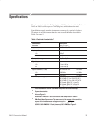
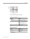
Table 6: Probe bandwidths
Probe type
2465 Oscilloscope
7A42 Plug-in
2445 Oscilloscope
1.3 meter length 300 MHz 150 MHz
2.0 meter length 250 MHz 150 MHz
7. If the generator frequency readout is less than the specified value, perform
the low-frequency and high-frequency compensation adjustments beginning
on page 10.
8. Disconnect the test setup.
To check the probe attenuation accuracy do the following:
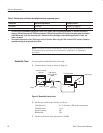
1. Connect the calibration generator standard amplitude output to the test
oscilloscope vertical input with the precision coax cable.
2. Set the calibration generator controls as follows:
Amplitude Standard
Output 50 mV
Frequency 1 kHz
3. Set the oscilloscope controls as follows:
Volts /Division 10 mV
Time/Division 10 ms
Input Coupling DC
Triggering Obtain a stable display
4. Adjust the calibration generator variable amplitude control to produce a
precise 5-division display on the oscilloscope.
5. Note the oscilloscope deflection error directly from the calibration generator
display for the calculation in step 9 below (Example: +1%).
Attenuation Accuracy
Check


