P6131 Instruction Manual
7
Service Information
WARNING. The following instructions are for use by qualified service personnel
only. To avoid electrical shock, do not disassemble or maintain the probe while it
is connected to a signal source other than those specified in this procedure.
This section contains detailed performance checks, adjustments, and mainte-
nance procedures. These procedures use external traceable test equipment to
directly check warranted characteristics. If you substitute equipment, always
choose instruments that meet or exceed the minimum specified requirements.
Performance Verification Procedure
Use the following procedure to verify that P6131 probe performs as warranted.
For a list of the warranted specifications, see page 3.
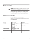
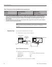
Table 5 lists the test equipment needed to perform the performance verification
and adjustment procedures.
Table 5: Performance verification and adjustment test equipment
Description Minimum requirements Example product
Oscilloscope
2
The P6131 probe is designed specifically for use
with Tektronix 2445 and 2465 oscilloscopes and
the 7A42 plug-in.
Tektronix 2445, 2465, or 7A42 plug-in
3
Calibration generator Pulse Rise Time: ≤1 ns
Amplitude: ≥0.5 V into 50 W
Rep Rate: 100 kHz
Accuracy: ±0.25%
Direct error readout
Wavetek 9500 High-Performance
Oscilloscope Calibrator
Leveled sine wave generator Amplitude: adjustable to 1 V
p-p
into 50 W
Frequency range:1 MHz to 300 MHz
2
Fixed 50 kHz reference
Precision coaxial cable 50 W BNC, 36 inch length Tektronix 012-0482-XX
10X attenuator 50 W BNC Tektronix 011-0059-XX
Adapter Subminiature probe-tip-to-BNC male Tektronix 013-0195-XX


