Appendix D: Factory Initialization Settings
Appendices
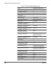
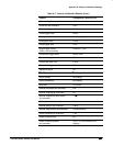
Table A-7: Factory Initialization Defaults (Cont.)
Control Changed by Factory Init to
Logic state trigger Ch4 (Ax2) input Rising edge
Logic trigger input
(pattern and state)
Channel 1 = H (high),
Channels 2 & 3 (Ax1) = X (don’t
care)
Logic trigger pattern time qualification
Lower limit
Upper limit
5 ns
5 ns
Logic trigger threshold (all channels)
(pattern and state)
1.2 V
Logic trigger class Pattern
Logic trigger logic
(pattern and state)
AND
Logic trigger triggers when ...
(pattern and state)
Goes TRUE
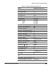
Main trigger holdoff 0%
Main trigger mode Auto
Main trigger type Edge
Math1 definition Ch 1 + Ch 2
Math1 extended processing No extended processing
Math2 definition Ch 1 – Ch 2 (FFT of Ch 1 on
instruments with Option 2F Ad-
vanced DSP Math)
Math2 extended processing No extended processing
Math3 definition Inv of Ch 1
Math3 extended processing No extended processing
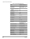
Measure Delay to Channel 1 (Ch1)
Measure Delay edges Both rising and forward searching
Measure High-Low Setup Histogram
Measure High Ref 90% and 0 V (units)
Measure Low Ref 10% and 0 V (units)
Measure Mid Ref 50% and 0 V (units)
Measure Mid2 Ref 50% and 0 V (units)
Pulse glitch trigger polarity Positive


