


10
PIA STROBING
Use of the Control Interface for Read/Punch-On/Off Decoding
SWTBUG® software contains subroutines to send out pulses to unused pins of the PIA
integrated circuit on the MP-C serial control interface that can be used for automatic reader /
punch controls. These pulses can be used if you are using a SWTPC AC-30 cassette interface
and a terminal in which access to the control command decoding is denied.
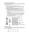
If you intend to use the read/punch control logic output on the MP-C control interface board,
make the following connections from the indicated pins of ICI on the MP-C control interface board
to the specified pins of a twelve pin male connector shell. The connector pinning shown below is
correct for a SWTPC AC-30 cassette interface and will need modifications for other units. Be sure
to make the wires long enough to reach your AC-30 where the connector will be plugged. If you
have access to your terminal’s 16X baud rate clock, the terminal’s clock bus should be broken
and the 16X clock IN and OUT lines brought out to the same connector.
MP-C IC1 pin 7 (read on) 12 pin male shell female pin 1
MP-C IC1 pin 4 (punch on) 12 pin male shell female pin 2
MP-C IC1 pin 6 (read off) 12 pin male shell female pin 3
MP-C IC1 pin 5 (punch off) 12 pin male shell female pin 4
Terminal’s 16X clock OUT 12 pin male shell female pin 5
Terminal’s 16X clock IN 12 pin male shell female pin 6
MP-C ground 12 pin male shell female pin 12
These signals are low going pulses and are about 15 microseconds wide. They are not
buffered and should drive a maximum of only one standard TTL load.
PIA stroking will work only on SWTBUG®‘s L, P and E functions. Strobing is not supported
in BASIC and some other SWTPC software.
OPERATING THE MP-A2 PROCESSOR BOARD
AT BAUD RATES HIGHER THAN 1200 BAUD
The MP-S Serial Interfaces available for the SWTPC 6800 Computer System are capable of
operating at baud rates up to 9600 baud. Although baud rate clocks for 110, 150, 300, 600 and
1200 baud are generated, buffered and fed onto the mother board by IC4 of the MP-A2 board,
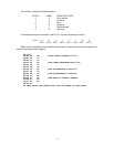
clocks for additional baud rates are also available from IC4 as well. The table below gives the
baud rate and respective output pin number of IC4.
BAUD RATE MP-A2 IC4 pin
75 9
200 6
1800 15
2400 3
3600 16
4800 2
7200 17
9600 1
To use the selected clock, run an insulated jumper between the specified pin and pin 13 of
IC10 on the MP-A2 board. Run another insulated jumper between pin 12 of IC10 and either the
UD1 or UD2 bus connections points at the connector edge of the MP-A2 circuit board. IC10 is a
low power TTL buffer which must be inserted between the baud rate clock generator and the
mother board bus. Since user defined lines UD1 and UD2 are carried on just the 50-pin main
board bus and lines UD3 and UD4 are carried on just the 30-pin interface board, it will be
necessary to jumper two of the buses together to provide the selected baud rate clock on the
interface card bus. Each serial interface card to be operated with the selected baud rate clock will
have to be jumpered so its clock is acquired from the selected user defined line rather than one of
the five original baud rate clocks already present.