


9
VECTORED SOFTWARE INTERRUPTS
Normally when encountering a SWI (3F) instruction, the computer will display the
processor’s registers and SWTBUG® control will be resumed. If desired, the 3F command can be
vectored to anywhere in memory, just like the NMI and IRQ interrupts. To use the vectoring
capability simply store the service routine address at location A012-A013 in the SWTBUG® RAM.
When a 3F is encountered, processor control will be transferred to the memory address stored in
A012-A013. Note: each time the system is RESET, A012 will be reset to the location of the
register dump routine. This means that any program which uses vectored SWl’s should set up
this location each time it is executed. If the location you wish to vector to is 10D0, for example,
the following statements at the beginning of the program will set up the vector correctly:
LDX # $10D0 LOAD VECTOR ADDRESS
STX $A012 STORE VECTOR
Vectored software interrupts should not be used in conjunction with breakpoints since the
breakpoint routine uses locations A012-A013.
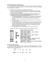
VECTORED INPUT/OUTPUT
If desired, input and output can be vectored to a MP-S or MP-C interface on ports other than
#1. Locations A00A-A00B contains the port address that the subroutines INEEE and OUTEEE
use for inputting and outputting characters. To use vectored input/output your program must store
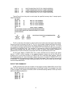
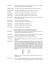
the desired I/O address in A00A–A00B before any I/O is done. Below is a list of I/O address
assignments for each port:
PORT ADDRESS
0 8000
1 8004
2 8008
3 800C
4 8010
5 8014
6 8018
7 801C
The program statements that would set up the correct port would be as follows:
LDX #$8018 I/O on port 6
STX $A00A Store
SWTBUG® will look at the port and will self-configure for either a MP-C or MP-S type
interface.
NOTE: Any time that SWTBUG‘s control sequence is initiated or when the RESET button is
pushed, the I/O address will be reset to port # 1. Therefore complete SWTBUG® monitor control
cannot be moved to another port.
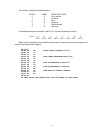
USING NON-MASKABLE INTERRUPTS
Using non-maskable interrupts is very similar to using vectored software interrupts. A non-
maskable interrupt will occur whenever the NMI line on the computer’s bus is grounded either
through hardware or by an ACIA or PIA. When the NMI is seen, processor control will be
transferred to the location stored in A006 and A007. For example if an NMI service routine is
desired at location 1000 the following statements should be used at the beginning of your
program to set up the correct NMI jump address.
LDX #$1000
STX $A006
USING MASKABLE (IRQ) INTERRUPTS
Using regular maskable interrupts is the same as using non-maskable interrupts except that
when the IRQ line is grounded processor control will jump to the address stored in A000 and
A001. The computer will only respond to the interrupt if the processor’s interrupt mask bit 1 is 0. A
CLI instruction at the beginning of your program will insure this condition.