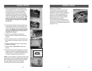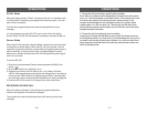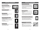
Flood Sensor:
FS-101
Audio Sensor:
AS-101
Garage Door
Monitor
TM
Sensor
GS-101
–6–
OVERVIEW
Dial Alert AD-105 must work with the specific sensors listed below. Ensure only the
listed sensors are used with the AD-105, otherwise, the communication between the
sensors and the Dial Alert may not function properly. If you have a Skylink wireless
device or sensor that is not listed below, and uncertain whether it can work with
your AD-105, please contact our customer support team.
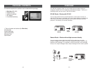
You can program the following sensors and accessories to the dialer, they are
fully compatible with Dial Alert AD-105:
Panic Devices
4-Button Transmitter: 4B-101, 4B-434
Panic Transmitter: PT-434, HW-434
Keypad Transmitter: KP-434
Control Panel: SC-001
Sensors
Door Window Sensor:
WD-101
Motion Sensor:
PS-101
Temperature Sensor:
TS-101A
Vibration Sensor:
VS-101
There are 2 types of sensors and accessories.
Panic Devices - These are devices such as 4-Button Transmitter, Panic
Transmitter and Keypad Transmitter. When the panic button on these
transmitters is activated, the Dial Alert will dial out regardless whether it is in
armed or disarmed mode.
Sensors - These sensors will only trigger the Dial Alert if it is armed. If the Dial
Alert is not armed, the Dial Alert will not be activated even if the sensors are
triggered. If you have sensors installed, ensure you arm the Dial Alert if you
want to be notified by sensor activation.
Please refer to the programming instructions “STANDARD PROGRAMMING” to
set up the operation mode of your emergency dialer.
–7–
INSTALLATION
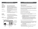
The Dial-Alert is installed using the screws provided. We have also included
double sided tape, to use for temporary installation while you are positioning
the dialer. Once the dialer is positioned correctly, install it permanently with
screws. We have also included wall anchors and a template to help position
the screws correctly.
How to use the template:
1. Cut the template in the correct position
2. Screw part way into the surface where the holes are marked
3. Unscrew the screws and remove the template
4. Screw the component in place where you started the screws
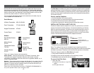
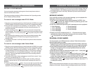
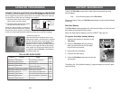
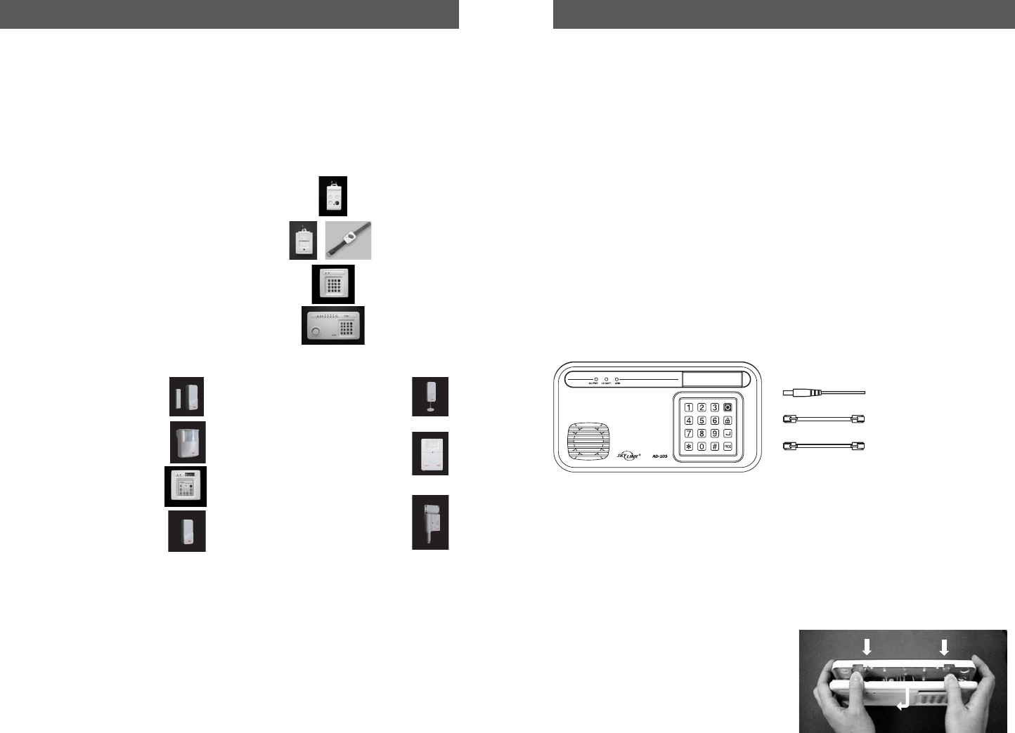
INSTALLING THE DIAL-ALERT (AD-105)
Position the dialer beside a telephone or near any phone line and within
access of an electrical outlet. However, it is recommended that you hide the
dialer for security purposes. The dialer runs on regular electrical current. It
also contains a 9 volt backup battery in case power is interrupted for any
reason. A phone line must be connected to the dialer in order for the dialer
to work. Connect the phone lines and AC adapter as shown.
Note: The optional line input is intended for an answering machine,
telephone etc. The device connected to the dialer will be disconnected when
the dialer is activated. Therefore it will not affect the operation of the dialer.
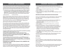
There are 3 ways to attach the Dial-Alert on the wall:
1. Using double sided tape for temporary use.
2. Hanging it from the two keyholes on two stationary screws.
3. Screwing the back onto the wall with four screws.
To mount the Dial-Alert:
1. Open the case.
a) Press the two tabs on top of the
dialer.
b) Pull open the front.
12V DC
AC ADAPTER
OPTIONAL LINE INPUT FOR
PHONE ANSWERING MACHINE / TELEPHONE
TEL LINE IN
LINE
905-456-8883


