


22 www.quantumrehab.com Quantum 500
V. COMFORT ADJUSTMENTS
COMFORT ADJUSTMENTS
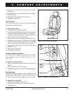
After becoming familiar with your power chairs operation, you may find the need to make some adjustments to increase
your comfort, such as seat height and angle, armrest width, armrest angle and height, foot platform height and angle, and
controller position. The following adjustment instructions are for contour seating. If your power chair is equipped with a
specialty seating system, refer to the information provided in separate manauls.
WARNING! If your power chair was configured by your Quantum Rehab Specialist, please consult
your healthcare professional before making any adjustment that may degrade your power chairs
performance and safety by changing its center of gravity.
WARNING! Some power chair components are heavy. You may need assistance to lift or carry
them. Please refer to the specifications table for specific component weights before you
disassemble the power chair.
WARNING! Prevent injury. Remove the occupant from the power chair before making any
adjustments.
You may need the following to make comfort adjustments:
n metric/standard socket set and ratchet
n adjustable wrench
n metric/standard hex key set
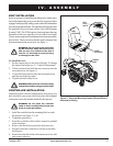
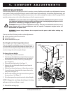
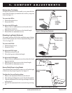
Seat Height and Seat Angle Adjustment
You can change the seat height to one of four positions in 1-
in. increments by raising the front and rear trapeze bars. If
you raise or lower only one trapeze bar (front or rear), you
can also change the seat base angle (dump).
To change the seat height:
1. Turn off the power to the controller.
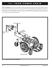
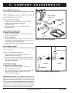
2. Turn the rear shroud fasteners counterclockwise one-quar
ter turn and remove the rear shroud cover. See figure 6.
3. Disconnect the controller connector(s) from the power
base. See figure 7.
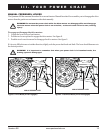
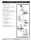
4. Flip up the seat latch safety. See figure 11.
5. Squeeze the seat latch and release the seat from the
front trapeze bar.
6. Slide the seat forward and remove it from the power base.
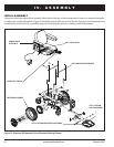
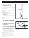
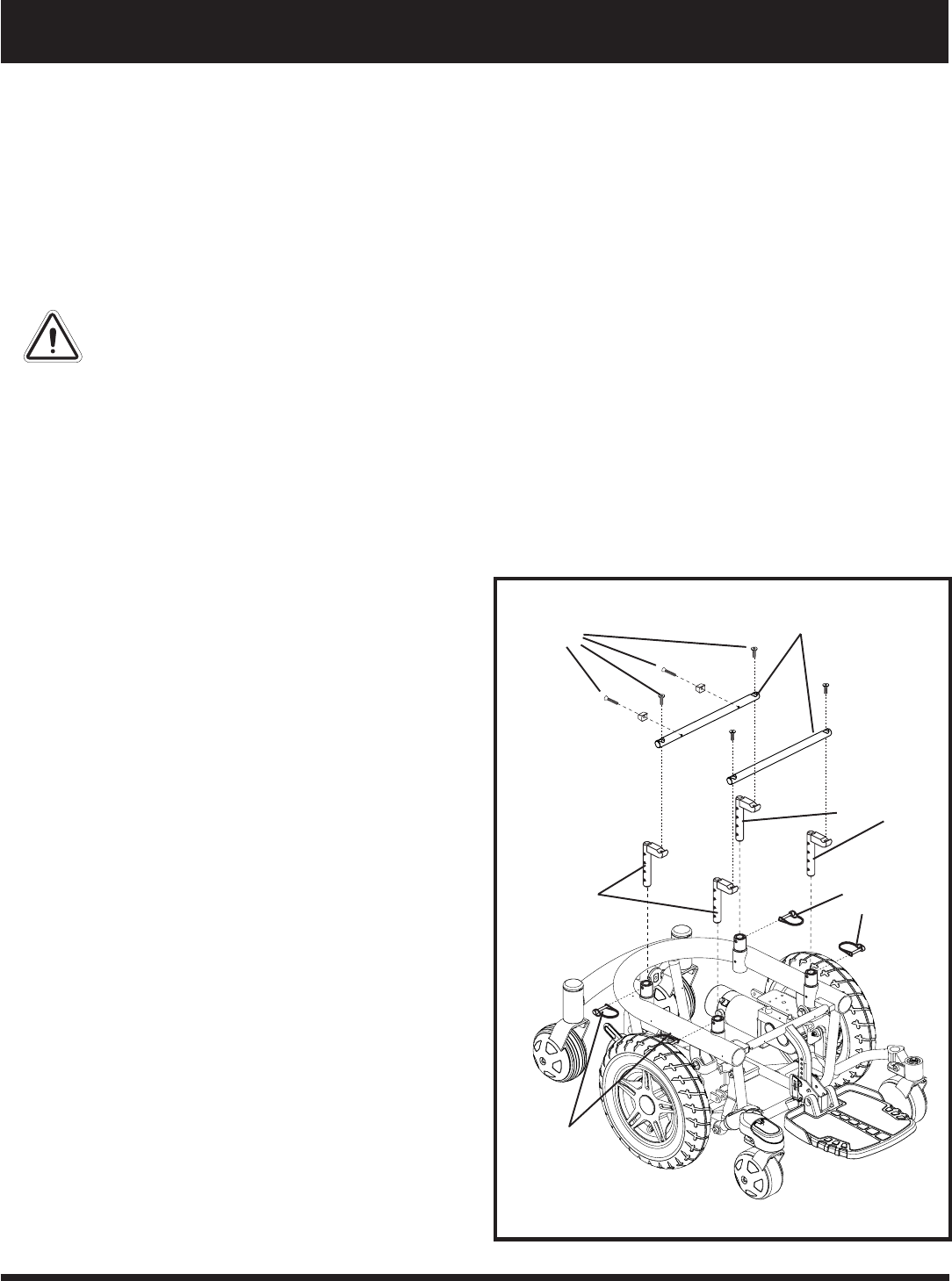
7. Loosen the screws that attach the trapeze bars to the
seat posts. See figure 12.
8. Remove the retaining clips that secure the seat posts to
the power base. See figure 12.
9. Move the trapeze bars up or down to the desired height.
NOTE: Change the seat dump by raising or lowering
only one set of towers (front or rear).
10. Reinstall the retaining clips.
TRAPEZE BARS
RETAINING
CLIPS
SEAT POSTS
Figure 12. Trapeze Bar Adjustment
SCREWS
SEAT POSTS
RETAINING
CLIPS