


Quantum 500 www.quantumrehab.com 21
IV. ASSEMBLY
SEAT INSTALLATION
It may be necessary to install the seat either prior to initial opera-
tion or after transporting your power chair. If your power chair is
equipped with a specialty seating system, refer to the information
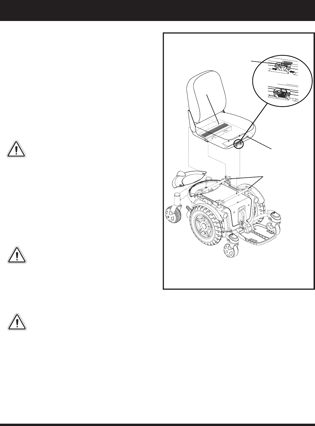
provided in separate manuals. The medium- and high-back seats
are attached to the power base with the Universal Mounting
System (UMS). The UMS consists of universal parts that may
be attached to the seat, regardless of seat width or seat depth.
The two main components are aluminum extrusions mounted to
the seat base. These extrusions attach to a pair of trapeze bars
that are mounted to the power base. See figure 11.
WARNING! Do not pick up the seat frame
by the armrests. They are free to pivot,
and you may lose control of the seat if
they do so, resulting in personal injury
or damage to the chair.
To install the seat:
1. Set the trapeze bars to the desired height. To change
the trapeze bar height, see V. Comfort Adjustments.
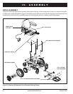
2. Tilt the seat back and slide the rear extrusion onto the
rear trapeze bar. See figure 11.
3. Lower the front extrusion onto the front trapeze bar
until the seat locks into place.
4. Flip the seat latch safety down.
WARNING! Make sure the seat latch safety
is flipped down before using your power chair.
CONTROLLER INSTALLATION
Depending on the various configurations and options you
have chosen for your power chair, it may have been shipped
without the controller module installed in the armrest.
WARNING! Do not place the controller
cable so that it can be pinched in the seat
frame or power base frame.
1. Install the controller into the mounting block or under
the armrest. See figure 17 or 18.
2. Tighten the setscrew(s).
3. Route the controller cable so that it cannot be pinched
in the seat hinge.
4. Remove the rear lid to expose the electronics tray.
5. Plug the controller connector(s) into the power base.
See figure 6.
6. Secure the controller cable to the armrest receiver with
one or more wire ties.
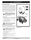
Figure 11. Universal Mounting System (Shown Without
Armrests for Clarity)
SEAT
LATCH
SAFETY
REAR
EXTRUSION
FRONT
EXTRUSION
TRAPEZE
BARS