


36 www.pridemobility.com Jet 10/Rev H/Feb03
X. CARE AND MAINTENANCE
MONTHLY CHECKS
n Check that the anti-tip wheels are not rubbing the ground when you are operating the Jet 10. Adjust them as
necessary. See VI. Comfort Adjustments.
n Check for extreme wear on the anti-tip wheels. Replace them as necessary.
n Check for drive tire wear. See an your authorized Pride provider for replacement.
n Check the rear casters for wear. Replace them as necessary.
n Check the rear forks for damage or fluttering which indicates that they may need to be adjusted or have the
bearings replaced. See an your authorized Pride provider for repair.
n Keep your Jet 10 clean and free of foreign material, such as mud, dirt, hair, food, and drink.
YEARLY CHECKS
Take your Jet 10 to an authorized Pride provider for yearly maintenance. This helps ensure that your Jet 10 is
functioning properly and helps prevent future complications.
STORAGE
Your power chair should be stored in a dry place, free from temperature extremes. When storing, disconnect
the batteries from the Jet 10. See IX. Batteries and Charging.
WARNING! If you fail to store the unit properly, the frame can rust and the electronics can be
damaged.
CLEANING INSTRUCTIONS
CAUTION! Never hose off your power chair or place it in direct contact with water. Your Jet 10 has
a painted, ABS plastic body shroud that allows it to be easily wiped clean with a damp cloth.
CAUTION! Never use any chemicals to clean a vinyl seat, as they may cause the seat to become
slippery or dry out and crack. Use soapy water and dry the seat thoroughly.
WHEEL REPLACEMENT
Your Jet 10 is equipped with solid tires. Periodically check the tires for excessive wear. If your tire requires
replacement, you must replace the entire wheel assembly. Replacement wheel assemblies are readily available
at your authorized Pride provider.
Follow these easy steps for a quick and safe wheel replacement:
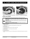
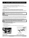
1. Use a 5/32-in. hex key to remove the hub cap. See figure 25.
2. Use an 11/16-in. wrench to remove the drive wheel nut from the center hub of the wheel. See figure 26.
3. Pull the wheel assembly off of the axle.
4. Slide the new wheel assembly back onto the axle.
5. Install the drive wheel nut into the center hub and tighten.
6. Install the hubcap.