


18 www.pridemobility.com Jazzy 1104 Rev F/Feb03
IV. THE JAZZY 1104
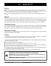
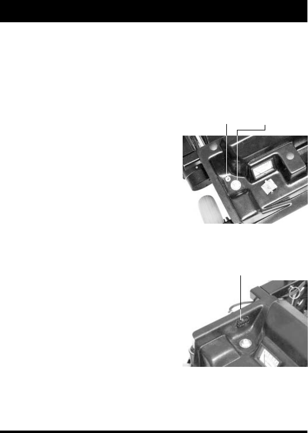
STANDARD HEADLIGHT/
TAILLIGHT CONNECTOR
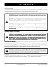
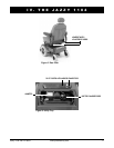
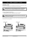
Figure 4. Main Circuit Breaker
MAIN CIRCUIT BREAKER
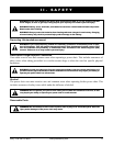
Figure 5. Full Lighting Harness Connector
FULL LIGHTING HARNESS CONNECTOR
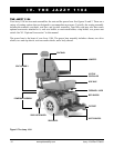
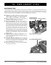
ELECTRONICS TRAY
The electronics tray is located on the rear of your Jazzy. See figure 3. A section of the electronics tray is
exposed through the body shroud. The rest of the electronics tray is located underneath the rear door. The
electronics tray consists of the ammeter, the battery charger cord, the main circuit breaker, the lighting
harness connectors (optional equipment), and the controller harness connectors.
n Ammeter: The ammeter displays the chargers current
output in amps. See figure 3. For more information,
see IX. Batteries and Charging in this manual.
n Battery Charger Cord: This cord is used whenever
your battery needs recharging. See figure 3.
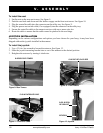
n Main Circuit Breaker: The main circuit breaker is a
safety feature built into your Jazzy 1104. See figure 4.
When the batteries and the motors are heavily strained
(e.g., from excessive loads), the main circuit breaker
trips to prevent damage to the motors and the electron-
ics. If the circuit trips, allow your Jazzy to rest for
approximately one minute. Next, push down the cir-
cuit breaker button, turn on the joystick controller and
continue normal operation. If the main circuit breaker
continues to trip repeatedly, contact your authorized
Pride provider.
n Lighting Harness Connector (Optional): This is
where the optional lighting harness connects to the con-
troller. See figure 5.
n Controller Harness Connectors: This is where the
joystick connects to the motors, batteries, and charger.
Your Jazzy is equipped with a Pilot controller. There
are two connectors on the tray. See figure 3.
n Power Seat Connector: This is for the optional power
seat switch. (Not shown.)