


22 www.pridemobility.com Jazzy 600 Series
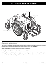
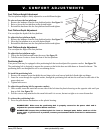
HARNESS ACCESS POINT
SIDE TABS
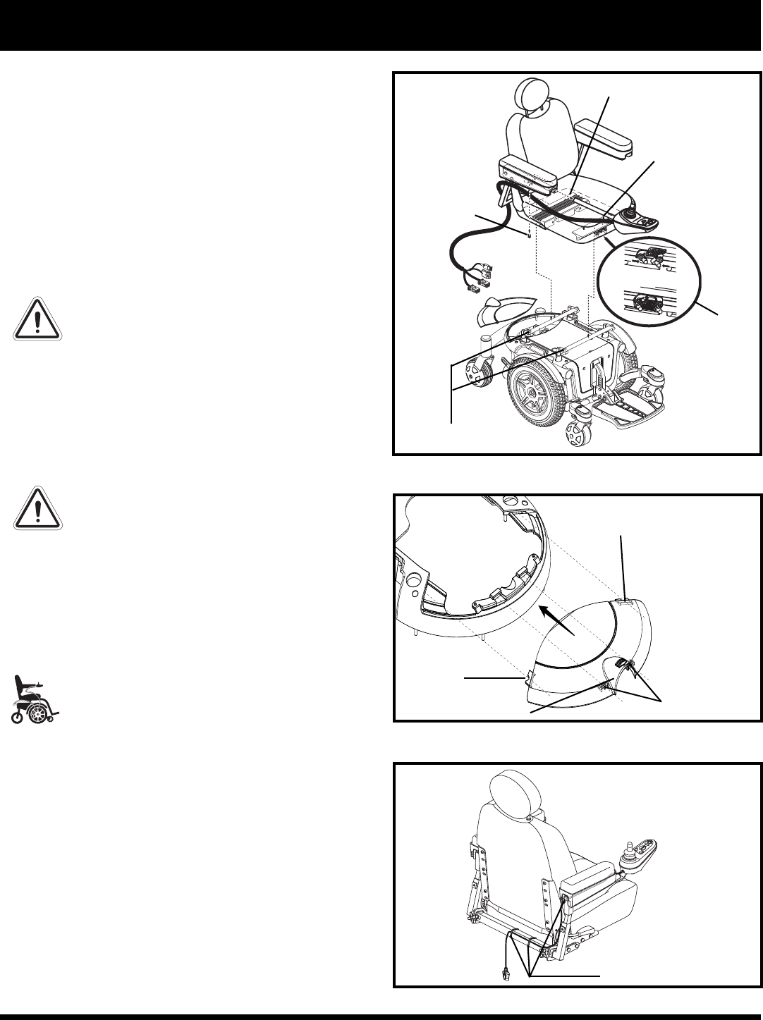
IV. ASSEMBLY
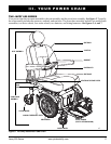
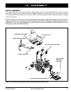
Seat Installation
It may be necessary to install the seat either prior to
initial operation or after transporting your power chair.
Most seats are attached to the power base with the Uni-
versal Mounting System (UMS). The UMS consists of
universal parts that may be attached to any medium-
back or high-back seat, regardless of seat width or seat
depth. The two main components are aluminum extru-
sions mounted to the seat base. These extrusions attach
to a pair of trapeze bars that are mounted to the power
base. See figure 11.
WARNING! Do not pick up the seat
frame by the armrests. They are free to
pivot, and you may lose control of the
seat if they do so.
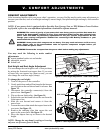
To install the seat:
1. Tilt the seat back and slide the rear extrusion onto
the rear trapeze bar. See figure 11.
2. Lower the front extrusion onto the front trapeze bar
until the seat locks into place.
3. Flip the seat latch safety down.
WARNING! Make sure the seat latch
safety is flipped down before using
your power chair.
4. Install the controller into one of the armrests.
Tighten the setscrew. See figure 11.
5. Route the controller harness so that it cannot be
pinched in the seat hinge.
MANDATORY! Prevent controller harness
damage! Avoid routing the controller har-
ness on the outside of the armrest pad.
Route the harness under the armrest or
toward the inside of the armrest pad. Use
correct tie-down points for the controller
harness to prevent the harness from get-
ting caught in the drive tires, pinched in
the seat frame, or damaged when passing
through doorways.
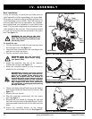
6. Gently push down and pull backward at the harness
access point on the rear shroud until it releases. See
figure 12.
7. Remove the rear shroud.
8. Plug the controller connector(s) into the power
base. See figure 7.
9. Reinstall the rear shroud by aligning the side and
back tabs with the holes in the main shroud. Gently
push down and forward until all four tabs lock into
place.
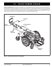
10. Secure the controller harness to the armrest
receiver with one or more wire ties. See figure 13.
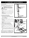
Figure 11. Universal Mounting System
SEAT
LATCH
SAFETY
Figure 12. Rear Shroud
SIDE TABS
BACK TABS
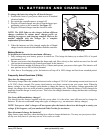
Figure 13. Controller Harness Routing
WIRE TIES
SETSCREW
REAR EXTRUSION
FRONT
EXTRUSION
TRAPEZE BARS