


22 www.pridemobility.com Quantum 6000 Series
IV. ASSEMBLY
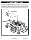
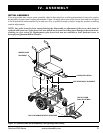
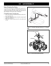
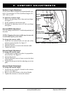
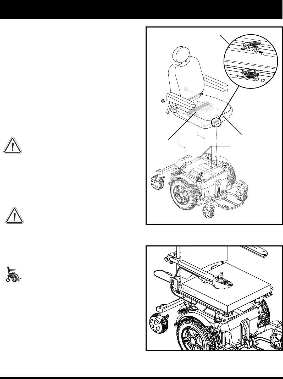
Figure 11. Universal Mounting System and Contour Seat
REAR
EXTRUSION
FRONT EXTRUSION
Seat Installation
It may be necessary to install the seat either prior to
initial operation or after transporting your power chair.
Contour seats are attached to the power base with the
Universal Mounting System (UMS). The UMS con-
sists of universal parts that may be attached to the seat,
regardless of seat width or seat depth. The two main
components are aluminum extrusions mounted to the
seat base. These extrusions attach to a pair of trapeze
bars that are mounted to the power base. See figure 11.
NOTE: If your power chair is equipped with a Spe-
cialty Seat, Synergy Seat, or a TRU-Balance Power
Positioning System, refer to the information provided
in separate manuals.
WARNING! Do not pick up the seat
frame by the armrests. They are free to
pivot, and you may lose control of the
seat if they do so.
To install the seat:
1. Tilt the seat back and slide the rear extrusion onto
the rear trapeze bar. See figure 11.
2. Lower the front extrusion onto the front trapeze bar
until the seat locks into place.
3. Flip the seat latch safety down.
WARNING! Make sure the seat latch
safety is flipped down before using
your power chair.
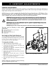
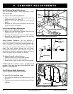
4. Install the controller and route the harness to the
back of the power base. See figures 12 and 13.
MANDATORY! Prevent controller
harness damage! Avoid routing the
controller harness on the outside of
the armrest pad. Route the harness
under the armrest or toward the inside
of the armrest pad. Use correct tie-
down points for controller harness to
prevent the harness from getting
caught in the drive tires, pinched in the
seat frame, or damaged when passing
through doorways.
5. Loosen the rear shroud fasteners and remove the
rear shroud. See figure 6.
6. Plug the controller connector into the power base.
See figure 7.
7. Replace the rear shroud and tighten the rear shroud
fasteners. See figure 6.
8. Secure the controller harness to the armrest
receiver with wire ties. See figure 13.
SEAT LATCH SAFETY
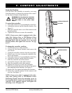
Figure 12. Controller Harness Routing on a Synergy
Seat
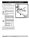
TRAPEZE BARS