


Quantum 6000 Series www.pridemobility.com 17
III. YOUR POWER CHAIR
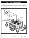
Electrical Components
The electrical components consist of the controller assembly, the batteries, and the motors. The batteries, motors,
and controller power module (if equipped) are located on the power base assembly. The controller is located on
the seat assembly. Connectivity between the controller and the motors, batteries, and the battery charger is pro-
vided by one or more wiring harnesses. See figure 7.
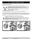
Controller Harness Connector: The controller harness connector is where the controller plugs into the power
base. Each controller uses a different type of harness. Regardless of which type of controller is used, the harness
must be secured to the seat assembly and not allowed to drag on the floor.
Motor Connectors: This is where the controller connects to the motors.
Battery Connector: This is where the controller connects to the batteries.
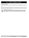
Controller Power Module: This enables the controller to communicate with the batteries and the motors.
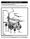
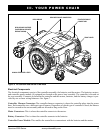
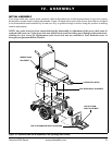
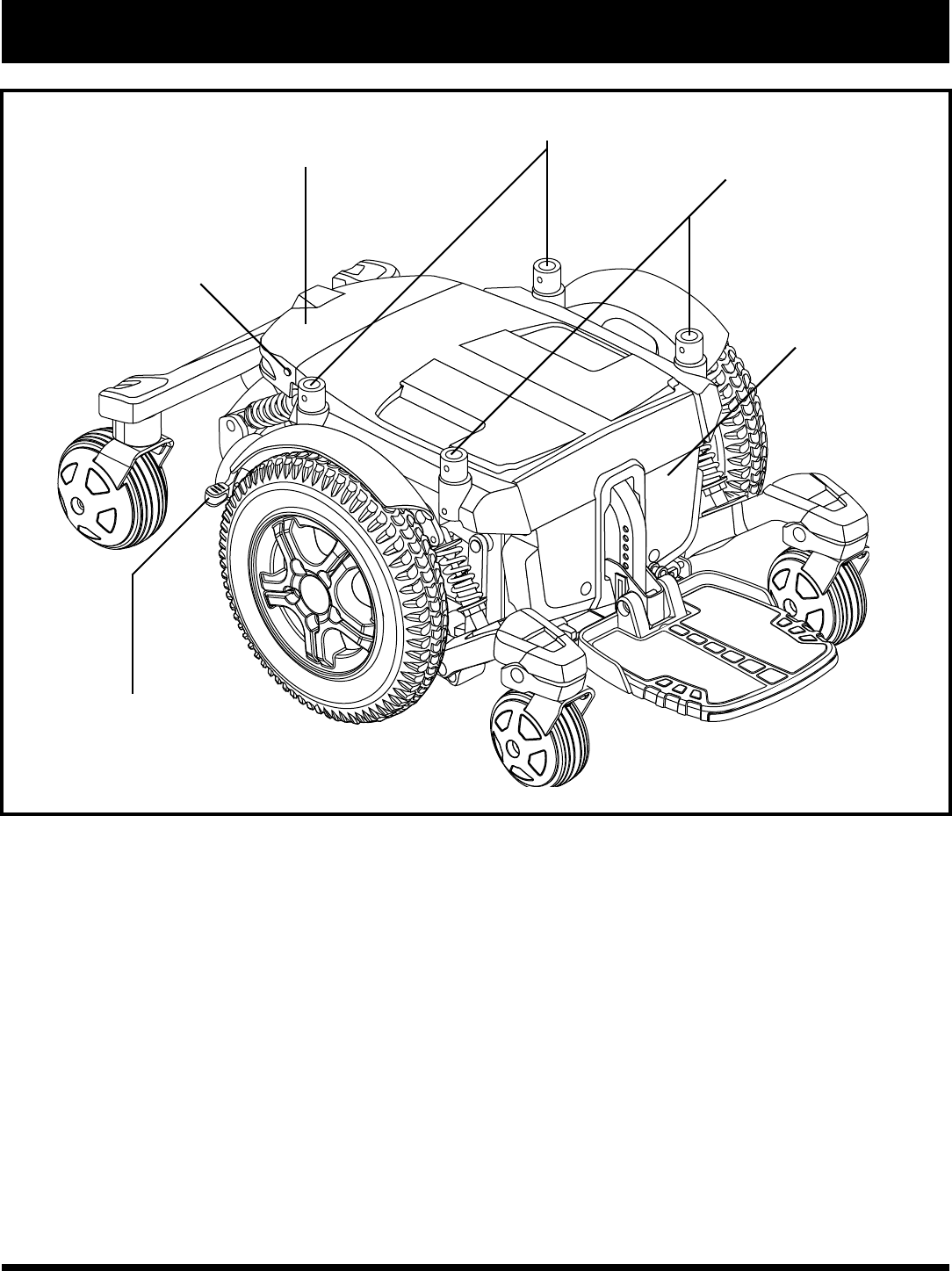
Figure 6. The Quantum 6000 Series Power Base
MANUAL FREEWHEEL LEVER
REAR SEAT MOUNT CONNECTORS
FRONT SEAT MOUNT
CONNECTORS
FRONT COVER
REAR SHROUD FASTENER
(FASTENER ON OPPOSITE
SIDE NOT SHOWN)
REAR SHROUD