


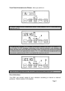
If using a shorter leadout from the probe or thicker gauge cable, please
ensure that the DP97 is in the correct wire recognition mode. This can be
checked by pressing the SPAN ss button ONCE.
Two numbers will be displayed e.g. 3-4. The first digit being the X
parameter (e.g.3) and the second digit being the Y parameter (e.g.4).
These displayed numbers will only be displayed momentarily.
Caution, pressing the SPAN ss button more than once or holding it down
continuously will alter the X-Y setting.
X Parameter
This is a configurable parameter. If the probe configuration is 4 wire but
has a lead resistance of less than 80mΩ per leg, he instrument may
recognise it as a 3 wire probe (showing 3-3); the SPAN ss may be used to
force the instrument into a 4 wire measurement mode by pressing SPAN
ss until X = 4. To verify, allow the DP97 to ead the currently selected
channel and press SPAN ss once; the display will now show 4-4.
X = 3 3 or 4 wire mode is allowable on either channel A or B i.e. A4, B3 or A3,
B4 or A3, B3 or A4; B4 (if both probes are 4 wire). I.e. 3 or 4 wire auto
Selected.
X = 4 4 wire mode is mandatory on both channels A & B I.E. A4, B4.
Y Parameter
The Y parameter gives the actual measuring mode of the currently
selected channel (except differential).
Y = 3 3 wire measuring
Y = 4 4 wire measuring
Differential Mode
In A-B mode the SPAN ss figure is not to be relied upon because the values
displayed will be for the last channel which has been read by the instrument and
this could be A OR B.
In order to verify status of each channel, select the channels A and B individually.
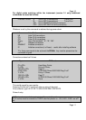
4. INSTRUMENT RE-CALIBRATION
Re-calibration of the DP97 is unlikely to be required routinely unless specified by user
regulations. If this is performed by someone other than the supplier, guarantee of
specification compliance may be invalid.