


iii) Matching DP97 to Calibrated Sensors
It is possible to automatically match the DP97 to a Pt100 sensor with up to
10 dedicated calibration values. Such values, published in an associated
certificate indicate true Ω versus °C values corresponding to accurately
known reference temperatures. Up to 10 sets of values per sensor can be
fed into the instrument via the RS232 interface using the associated
software supplied with each version 2.1 instrument as standard.
By matching the instrument to a probe on this basis, “corrected”
temperature readings are obtained directly without the need for cross-
referencing to temperature/resistance tables or to the calibration
certificate. This is particularly helpful when taking differential (A-B)
readings.
Refer to sections 6 and 7 for details.
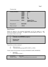
iv) Error Indications
The DP97 has several modes of error indication according to internal or
external problems as follows:
Display Cause
Err 1 Calibration lost (very unlikely)
Err 2 Software fault
Err 3 Broken probe connection
Err 4 RS 232 command error
BAtt “Low” battery
Or Over-range input
Ur Under-range input
Only Err 1 / Err 2 would require returning the instrument to our factory.
Note: During normal operation, if a selected probe is disconnected from the
instrument the display will indicate Err 3 (broken probe indication). If the same probe is
re-connected, Err 3 will remain on the display until any key is pressed.
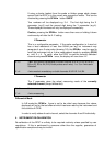
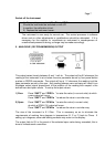
v) ¾ Wire Recognition
DP97 requires a minimum of 80mΩ lead resistance (eg. 1 metre of 7
stranded 0.2 mm² wire) to recognise a 4 wire probe. Otherwise the
instrument will default (perhaps incorrectly) to 3 wire mode.
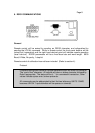
If a simulator is used to apply resistance values to check or calibrate the
DP97 ensure that at least 80mΩ of lead resistance exists between the
simulator and the D plug.
Page 5