


vi
List of Figures
Figure
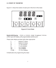
Figure 2-1. Front-Panel . . . . . . . . . . . . . . . . . . . . . . . . . . . . . . . . . . . . . . . . . . . .5
Figure 2-3. Connector Label (AC-Powered and DC-Powered Detail) . . . . . . . . . . .9
Figure 3-1. Main Board Power Jumpers (W1, W2, W3) . . . . . . . . . . . . . . . . . . . .12
Figure 3-2. Main Board Jumper Positions . . . . . . . . . . . . . . . . . . . . . . . . . . . . . .13
Figure 3-3. Upper Option Board Installation . . . . . . . . . . . . . . . . . . . . . . . . . . . .13
Figure 3-4. Meter - Exploded View . . . . . . . . . . . . . . . . . . . . . . . . . . . . . . . . . . .15
Figure 3-5. Panel Cut-Out . . . . . . . . . . . . . . . . . . . . . . . . . . . . . . . . . . . . . . . . . .15
Figure 3-6. 2-Wire RTD Input Connection . . . . . . . . . . . . . . . . . . . . . . . . . . . . . .16
Figure 3-7. 3-Wire RTD Input Connection . . . . . . . . . . . . . . . . . . . . . . . . . . . . . .16
Figure 3-8. 4-Wire RTD Input connection . . . . . . . . . . . . . . . . . . . . . . . . . . . . . .16
Figure 3-9. Main Power Connections - AC Powered Unit . . . . . . . . . . . . . . . . . . .17
Figure 3-10. Main Power Connections - DC Powered Unit . . . . . . . . . . . . . . . . . .18
Figure 3-11. Relay Output Connections . . . . . . . . . . . . . . . . . . . . . . . . . . . . . . .18
Figure 3-12. Analog Output Connections. . . . . . . . . . . . . . . . . . . . . . . . . . . . . . .19
Figure 3-13. Isolated Analog Output Connections. . . . . . . . . . . . . . . . . . . . . . . . .19
Figure 4-1 Proportional Band . . . . . . . . . . . . . . . . . . . . . . . . . . . . . . . . . . . . . . .29
Figure 12-1. Meter Dimensions . . . . . . . . . . . . . . . . . . . . . . . . . . . . . . . . . . . . . .53
List of Tables
Table
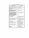
Table A-1. Sections of the Manual . . . . . . . . . . . . . . . . . . . . . . . . . . . . . . . . . . . . .ii
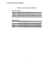
Table 2-1. Accessories and Add-Ons . . . . . . . . . . . . . . . . . . . . . . . . . . . . . . . . . .4
Table 2-2. Connector Description . . . . . . . . . . . . . . . . . . . . . . . . . . . . . . . . . . . .10
Table 3-1. S3 Jumper Functions . . . . . . . . . . . . . . . . . . . . . . . . . . . . . . . . . . . . .14
Table 3-2. Main Power Connections - AC Powered Unit . . . . . . . . . . . . . . . . . . . .18
Table 6-1. Truth Table for Display Values . . . . . . . . . . . . . . . . . . . . . . . . . . . . . .39
Table 8-1. Display Messages . . . . . . . . . . . . . . . . . . . . . . . . . . . . . . . . . . . . . . .42
Table 9-1. Configuration Menu . . . . . . . . . . . . . . . . . . . . . . . . . . . . . . . . . . . . . .43
Table 10-1. Front Panel Displays . . . . . . . . . . . . . . . . . . . . . . . . . . . . . . . . . . . .45
Table 10-2 Run Mode Displays . . . . . . . . . . . . . . . . . . . . . . . . . . . . . . . . . . . . . .48
Table 11-1. Setpoint Configuration Displays . . . . . . . . . . . . . . . . . . . . . . . . . . . .49
Table 13-1. Factory Preset Values . . . . . . . . . . . . . . . . . . . . . . . . . . . . . . . . . . .54