151
CHAPTER 6 COMMUNICATIONS AMONG CPU MODULES
6
6.1 Communications Using the CPU Shared Memory
6.1.3 Communications by programs using the CPU shared memory
(2) Instructions used to read/write data from/to the CPU shared memory
The QCPU in the multiple CPU system communicates data with other CPU modules by executing read/write
instructions. The following read/write instructions can be used.
*1 When accessing the multiple CPU high speed transmission area, the processing times of these instructions are shorter
than those of the TO, DTO, FROM, and DFRO instructions.
*2 With this instruction, data cannot be written to the user setting area in the multiple CPU high speed transmission area.
*3 For details on the TO/DTO/S.TO instructions (for writing) and the FROM/DFRO instructions (for reading), refer to the
following.
MELSEC-Q/L Programming Manual (Common Instruction)
*4 Motion CPUs do not support the use of these instructions.
(3) Addresses of the user setting area and multiple CPU high speed transmission
area
(a) Addresses of the user setting area
The addresses of the user setting area differ depending on the CPU module used. ( Page 118, Section
6.1)
(b) Addresses of the multiple CPU high speed transmission area
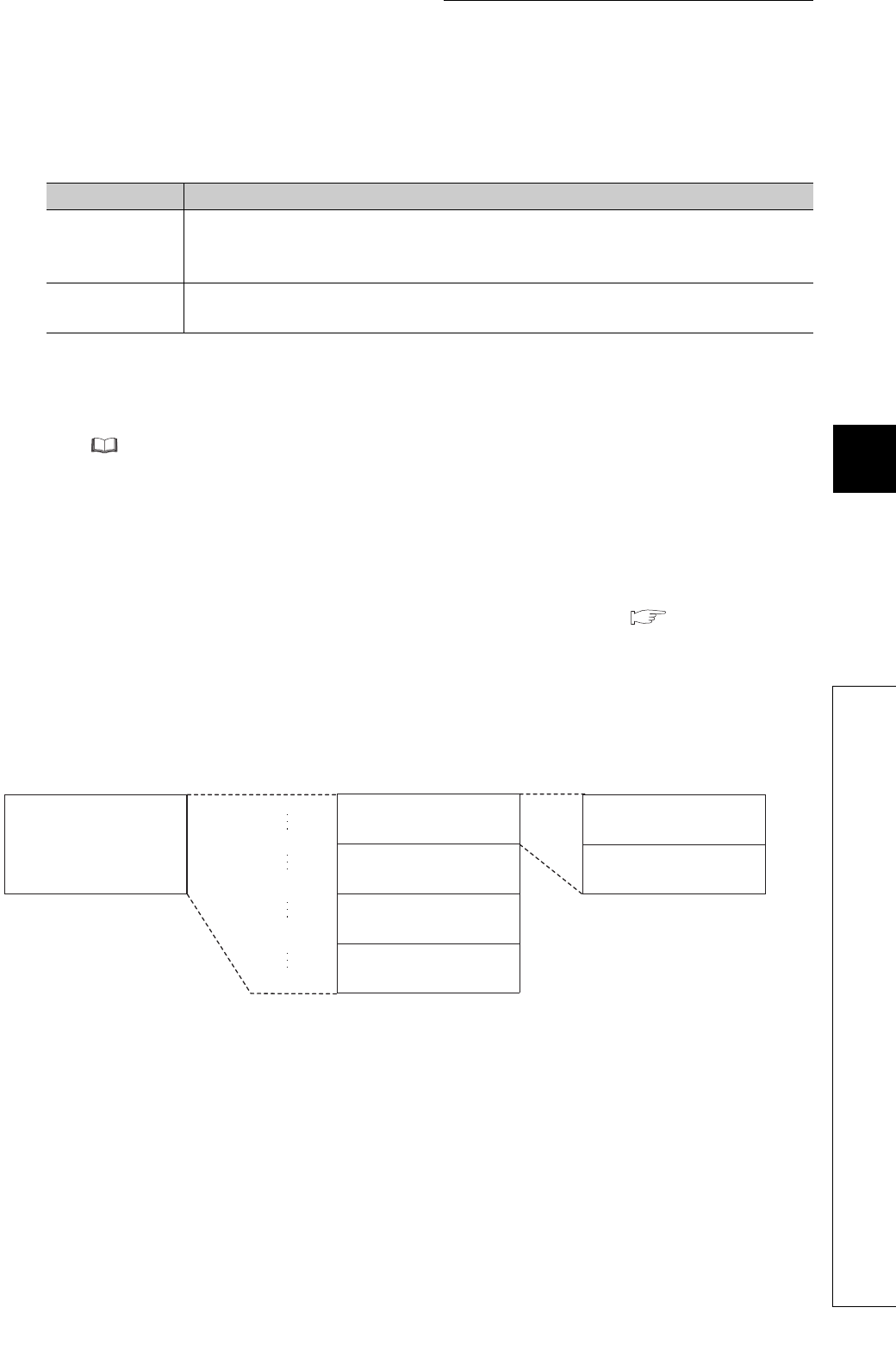
The addresses of the multiple CPU high speed transmission area are shown below. The end addresses of the
send areas in each CPU module differ depending on the number of points set in "CPU Specific Send Range" of
PLC parameter ("Multiple CPU Setting").
*1 These addresses are used to specify the user setting area of the target CPU module in the cyclic transmission area
device.
For details on each area in the multiple CPU high speed transmission area, refer to Page 135, Section 6.1.2.
Item Description
Write instruction
*3*4
• Instructions using the cyclic transmission area device (U3En\G)
*1
• TO/DTO instructions (except for High Performance model QCPUs and Process CPUs)
• S.TO instruction
*2
Read instruction
*3*4
• Instructions using the cyclic transmission area device (U3En\G)
*1
• FROM/DFRO instructions
Multiple CPU high
speed transmission area
U3E0\G10000 *1
U3E1\G10000 *1
U3E2\G10000 *1
U3E3\G10000 *1
CPU No.1 send area
CPU No.2 send area
CPU No.3 send area
CPU No.4 send area
User setting area
Auto refresh area


