


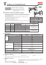

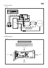

Wiring diagram
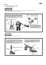
Wiring to Switch
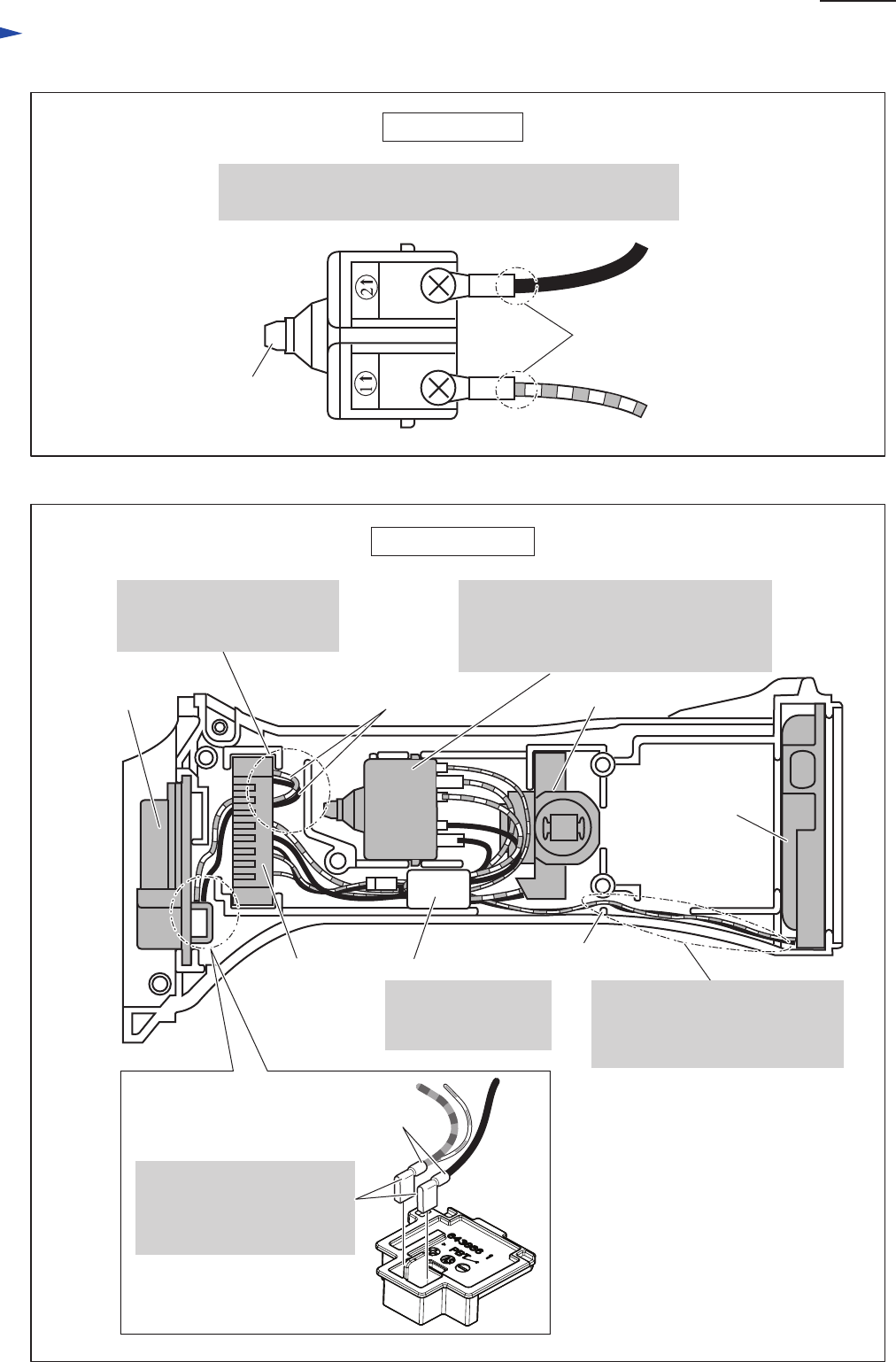
Wiring in Housing L
Switch button
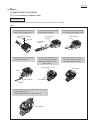
Set Switch to Housing L as follows:
* Face Switch button to Controller side.
* Face Insulated terminals connected side
(See Fig. 3D.) to Housing L.
Wire connecting portions
of Insulated terminal
Connect Insulated terminals to Switch while facing their wire
connecting portions to the opposite side of Switch button.
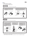
Controller
Lead wires of Controller
Put Line filter in the
space as drawn above
if it is used.
Line filter
Lead wire holder
Terminal Endbell complete
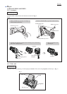
LED Circuit
Switch
Fig. D-3
Fig. D-4
Guide lead wires of LED circuit
along the wall side of Housing L
as drawn above. And then fix
the wires with Lead wire holder.
Wire connecting portions
Connect Flag connectors
so that their wire connecting
portions are located over
the mark of + - poles.
Pass Lead wires of Controller
through the space between
Housing L and Controller.
P 8/ 8