


98
FWD WHEELCHAIRSPROCEDURE 17
F
W
D
W
H
E
E
L
C
H
A
I
R
S
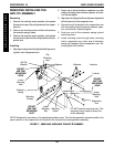
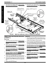
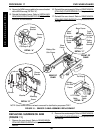
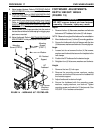
Tie Wrap A
Sensor
Cable
Sensor
Bracket
LEFT Motor
Cable
Sensor
Cable
Tie Wrap B
Battery
Box Sub-
Frame
“Lego”
Block
Connector
Of The
Battery
Wiring
Harness
Base Frame
Mounting
Screw
Washer
Locknut
Sensor
Sensor
Bracket
FIGURE 10 - SENSOR CABLE ASSEMBLY REPLACEMENT
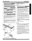
Tie Wrap C
Battery Box
Sub-Frame
Base
Frame
DETAIL “A”
DETAIL “B”
DETAIL “C”
DETAIL “D”
“Lego”
Block
Connector
Of The
Sensor
Cable
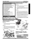
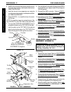
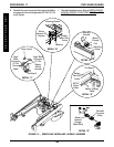
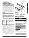
REPLACING SUSPENSION ARM
(FIGURE 11)
1. Remove the rear shroud. Refer to REMOVING/IN-
STALLING REAR SHROUD in this procedure of the
manual.
NOTE: Seat frame and drive wheels removed for clarification purposes ONLY.
REAR OF
CHAIR
FRONT OF
CHAIR
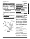
2. Remove the counterweight. Refer to
REMOVING/IN-
STALLING COUNTERWEIGHT in this procedure of
the manual.
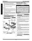
16. Reinstall the counterweight. Refer to REMOVING/IN-
STALLING COUNTERWEIGHT in this procedure of
the manual.
17. Reinstall the rear shroud. Refer to
REMOVING/IN-
STALLING REAR SHROUD in this procedure of the
manual.
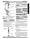
14. Secure the NEW sensor cable to the sensor bracket
with a NEW tie wrap (DETAIL “A”).
15. Reinstall the battery boxes. Refer to INSTALLING/
REMOVING GROUP 24 BATTERY BOXES in PRO-
CEDURE 9 of this manual.