


35
8. Secure the battery charger connector to the mount
bracket with the EXISTING two (2) mounting screws.
Tighten securely.
9. Reverse STEP 2A, 2B or 2C.
10. Perform the instructions outlined in
PREPARATIONS
FOR REMOVING/INSTALLING SEAT FRAME (STAN-
DARD FRAME, ADJUSTABLE FRAME, AND CAP-
TAINS VAN SEAT) in PROCEDURE 6 of this manual.
12. Reinstall the seat mount plates. Refer to
REPLACING
SEAT MOUNTING PLATES in this procedure of the
manual.
13. Adjust seat mounting plates to desired angle. Refer to
MOUNTING PLATE - SEAT ANGLE ADJUSTMENT
AND INSTALLATION ORIENTATION in PROCEDURE
6 of this manual.
14. Reverse STEP 2A, 2B or 2C.
15. Perform the instructions outlined in
PREPARATIONS
FOR REMOVING/INSTALLING SEAT FRAME (STAN-
DARD FRAME, ADJUSTABLE FRAME, AND CAP-
TAINS VAN SEAT) in PROCEDURE 6 of this manual.
REPLACING BATTERY CHARGER
BRACKET AND T-NUT
NOTE: There is no T-nut on the FWD models.
RWD and MWD Models (FIGURE 4)
1. Perform the instructions outlined in
PREPARATIONS
FOR REMOVING/INSTALLING THE SEAT FRAME
(STANDARD FRAME, ADJUSTABLE FRAME, AND
CAPTAINS VAN SEAT) in PROCEDURE 6 of this
manual.
2. Perform one (1) of the following:
A. Remove standard seat frame subassembly. Refer
to
REMOVING/INSTALLING STANDARD SEAT
FRAME SUBASSEMBLY in PROCEDURE 6 of
this manual.
B. Remove adjustable seat frame subassembly. Re-
fer to
INSTALLING/REMOVING ADJUSTABLE
SEAT FRAME ASSEMBLY AND OR COMPO-
NENT REPLACEMENT in PROCEDURE 6 of
this manual.
C. Remove captains van seat. Refer to
INSTALLING/
REMOVING CAPTAINS VAN SEAT ASSEMBLY in
PROCEDURE 6 of this manual.
3. Remove the seat support brackets. Refer to
RE-
PLACING SEAT SUPPORT BRACKETS in this
procedure of this manual.
4. Remove the two (2) mounting screws that secure the
battery charger connector to the mount bracket.
5. Remove battery charger connector from mount bracket.
6. Remove the mounting screw which secures the battery
charger mount bracket to the T-nut located in the chan-
nel of the base frame.
7. Replace battery charger mount bracket and secure to
base frame with existing mounting screw.
NOTE: To replace the Battery Charger Bracket T-Nut, per-
form STEPS 3-13 in
REPLACING SEAT SUPPORT
BRACKET T-NUTS in this procedure of the manual.
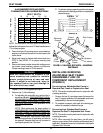
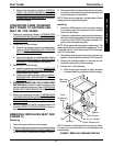
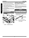
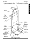
FIGURE 4 - RWD AND MWD MODELS
Battery
Charger
Connector
Battery
Charger
Mount
Bracket
Base
Frame
T-nut
Mounting Screw
BASE FRAME PROCEDURE 7
B
A
S
E
F
R
A
M
E
Arrow FWD Model (FIGURE 5)
1. Perform one (1) of the following:
A. For LOW MOUNT BRACKETS, perform
STEPS 1-11.
B. For MEDIUM/HIGH MOUNT BRACKETS per-
form STEPS 4-9 ONLY.
2. Perform the instructions outlined in
PREPARATIONS
FOR REMOVING/INSTALLING THE SEAT FRAME
(STANDARD FRAME, ADJUSTABLE FRAME, AND
CAPTAINS VAN SEAT) in PROCEDURE 6 of this
manual.
3. Perform one (1) of the following:
A. Remove standard seat frame subassembly. Refer
to
REMOVING/INSTALLING STANDARD SEAT
FRAME SUBASSEMBLY in PROCEDURE 6 of
this manual.
B. Remove adjustable seat frame subassembly. Re-
fer to
INSTALLING/REMOVING ADJUSTABLE
SEAT FRAME ASSEMBLY AND OR COMPO-
NENT REPLACEMENT in PROCEDURE 6 of
this manual.
C. Remove captains van seat. Refer to
INSTALLING/
REMOVING CAPTAINS VAN SEAT ASSEMBLY in
PROCEDURE 6 of this manual.
4. Remove the front shroud. Refer to
REMOVING/IN-
STALLING FRONT SHROUD in PROCEDURE 17
of the manual.