


3
USA/UK ENGLISH
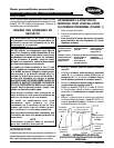
Clamp
Insert
BACK OF
WHEELCHAIR
Back
Cane
Slide Clamp
OVER Insert
Insert
Clamp
SIDE VIEW
Back Cane
TOP VIEW
BACK OF
WHEELCHAIR
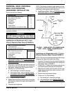
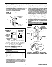
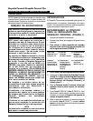
FIGURE 3 - INSTALLATION ON WHEELCHAIRS
WITH 7/8-INCH (22MM) DIAMETER BACK
CANES
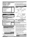
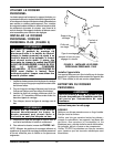
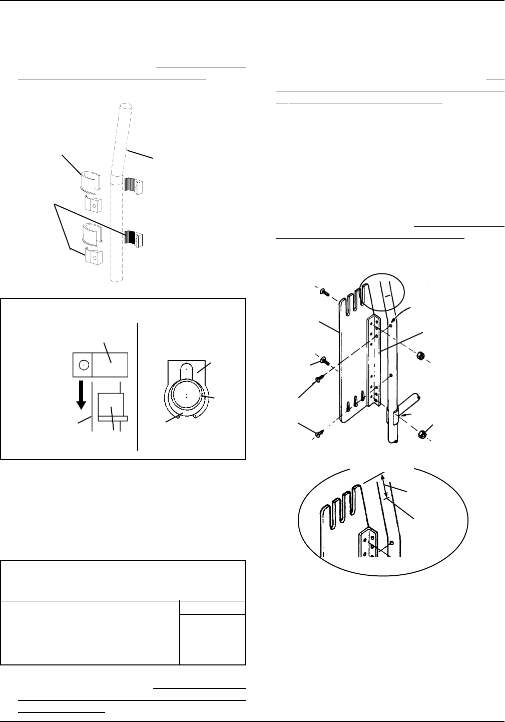
Installation on Wheelchairs Using L-Shaped
Brackets (FIGURE 4)
Have the following tools available:
Phillips Head Screwdriver
3/8-inch Crescent/Box Wrench
Parts Required: Quantity
Multi-Position Plate 2
L-Brackets 2
Short Phillips Head Bolts 4
Locknuts 4
1. Determine back height. Refer to DETERMINING THE
MOUNTING POSITION FOR INSTALLATION OF
PERSONAL BACK in this instruction sheet.
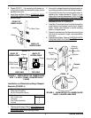
Insert
Clamp
Back Cane
FRONT OF
WHEELCHAIR
BACK OF
WHEELCHAIR
DETAIL "A"
2. Secure the L-shaped brackets to the back canes us-
ing existing upholstery holes and existing hardware.
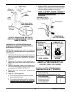
3. Ensure that the top of the mounting plate when in-
stalled to the L-shaped bracket is 1/2-inch (1.2 cm)
higher than the mark determined in STEP 8 of
DE-
TERMINING THE MOUNTING POSITION FOR IN-
STALLATION OF PERSONAL BACK in this instruc-
tion sheet (DETAIL "A", FIGURE 4).
4. Install two (2) short bolts (from the inside) through the
small holes on mouting plate, then through L-shaped
braket. Tighten down locknuts to secure mounting
plate to L-shaped bracket.
5. Repeat the procedure for the other side, ensuring that
both side are matched for height, and are parallel to
each other.
6. Install Personal Back. Refer to
PERSONAL BACK/
PERSONAL BACK PLUS INSTALLATION in this in-
struction sheet.
Outside
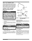
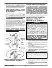
FIGURE 4 - INSTALLATION ON WHEELCHAIRS
USING L-SHAPED BRACKETS
Existing
Upholstery
Mounting Hole
Locknut
Short Bolt
Inside
L-Bracket
Existing
Hardware
Mark
1/2-inch
DETAIL "A"
Mounting
Plate
6. Repeat STEPS 1 - 4 for remaining half-clamps, en-
suring that both sides are matched for height, and are
parallel to each other.
7. Install Personal Back. Refer to
PERSONAL BACK/
PERSONAL BACK PLUS INSTALLATION in this in-
struction sheet.