


20 Part No. 1118395
®
WARNING
After ANY adjustments, repair or service and BEFORE use, make sure that
all attaching hardware is tightened securely. Otherwise, injury or damage
may result.
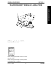
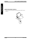
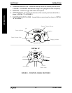
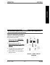
CONTROL PANEL FEATURES (FIGURE 1)
1. SPEED CONTROL KNOB - Located on the top face of the control panel. The Turtle
icon ( ) represents the slowest speed and the Rabbit icon ( ) represents the
fastest speed as shown in FIGURE 1.
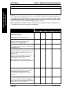
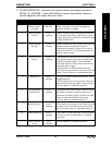
2. BATTERY CHARGE-INDICATOR (BCI) - The BCI is located on the top face of the
control panel as shown in FIGURE 1. The BCI is composed of eight (8) LED's - three
(3) green, three (3) yellow and two (2) red. It provides information on the remaining
battery charge. At full charge all eight (8) LED's will be lit. As the batteries becomes
discharged, the number of LED's will decrease from green to yellow then red. At this
level, the user should charge the batteries as soon as possible. See chart below.
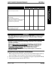
NOTE: The number of LED's bars may decrease when driving over uneven surfaces even with
batteries fully charged. To see an accurate true reading, insert the key and turn to the ON position
while the powered scooter is stationary.
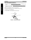
WARNING
When negotiating ramps, if the throttle control lever is released while in
FORWARD motion the powered scooter will "ROLLBACK"
approximately one (1) foot before brake engages. If the throttle control
lever is released while in REVERSE motion the powered scooter will
"ROLLBACK" approximately three (3) feet before brake engages.
Section 3 - Operation - includes the following:
Control Panel Features
Operation of the Scooter
Brake Release Lever
Reset Circuit Breaker/Fuse Replacement
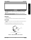
SECTION 3 OPERATION
OPERATION
LED'S ILLUMINATED CHARGE OF BATTERIES
All Fully Charged
Yellow and Red Partially Charged
Red Partially Discharged
(Charge batteries as soon as possible.
Refer to CHARGING THE BATTERIES
in SECTION 8 of this manual.)
None Fully Discharged