


SECTION 13—TRANSPORTING
300 and 400 62 Part No. 1118395
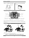
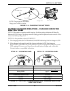
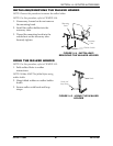
A. Use the one hand to firmly hold the tiller handle.
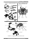
B. Using the other hand, firmly hold the YELLOW frame lock lever [located under
marker label # 2]and pull UP to the Unlocked position as shown in Detail “C” of
FIGURE 13.2.
NOTE: The frame lock lever remains in the unlocked position when the front frame assembly is
separated from the rear frame assembly.
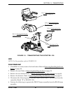
C. Lift the front frame assembly so that the mounting brackets disengages from the
rear frame assembly as shown in Detail “C” of FIGURE 13.2.
D. Separate the front frame assembly from the rear frame assembly.
7. Fold tiller down to lowest locked position. Refer to Adjusting the Tiller Angle on
page 43.
ASSEMBLING
1. Unfold tiller. Refer to Adjusting the Tiller Angle on page 43.
2. Ensure that the tiller is in the highest LOCKED position.
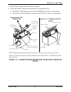
3. Perform the following to connect the front frame assembly to the rear frame assembly
(Detail “C” of FIGURE 13.2):
A. Use the one hand to firmly hold the tiller handle.
B. Using the other hand, firmly hold the front frame assembly and align with the
REAR frame assembly.
NOTE: The frame lock lever remains in the unlocked position when the front frame assembly is
separated from the rear frame assembly.
ƽ WARNING
When reassembling scooter, ensure the frame lock lever is in the LOCKED position
securing the FRONT and REAR frame assemblies together. Otherwise, injury and/
or damage may result.
C. Lower the front frame assembly so that the mounting brackets engage with the
rear frame assembly.
NOTE: The mounting brackets are engaged when an audible “click” is heard. The YELLOW frame
lock lever automatically locks in place.
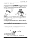
4. Connect the 4-housing motor connector [located under marker label # 1] to the
controller (Detail “B” of FIGURE 13.2).
5. Install the batteries. Refer to Removing/Installing the Batteries on 400 on page 53.
6. Install the rear shroud. Refer to Removing/Installing the Rear Shroud
on page 44.
7. Install the seat. Refer to Removing/Installing the Seat on page 34.
8. If desired, install the front basket. Refer to Removing/Installing the Front Basket
on
page 64.