


SECTION 7—SEAT
Part No. 1118395 37 300 and 400
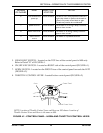
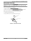
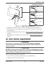
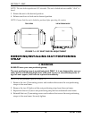
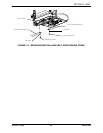
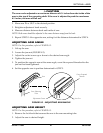
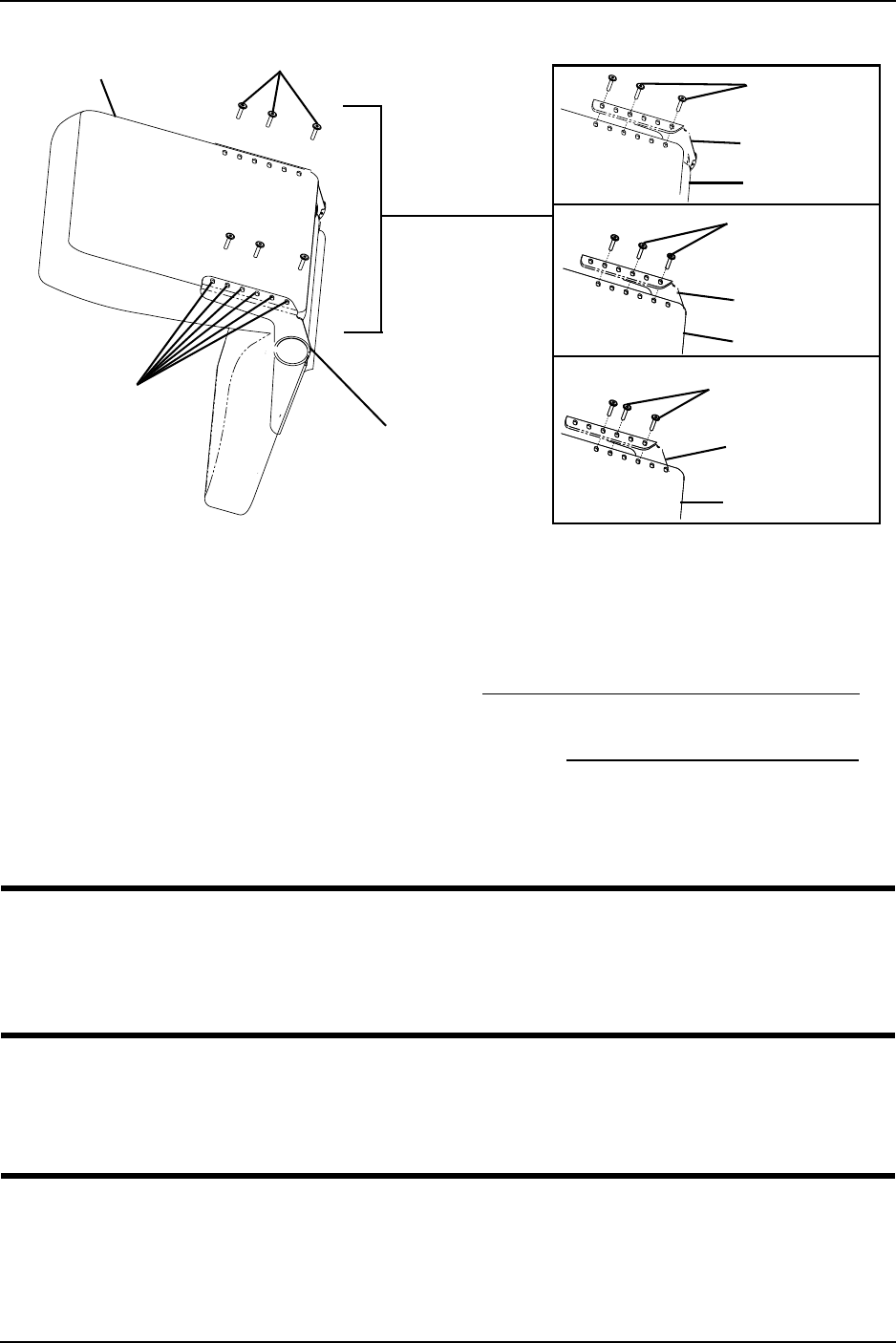
FIGURE 7.3 - ADJUSTING SEAT DEPTH
4. Adjust back assembly to one (1) of three (3) mounting positions (FIGURE 7.3).
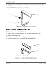
5. Reinstall the six (6) mounting screws securing the back assembly to the seat base.
Securely tighten.
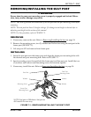
6. Reinstall the adjustable width arms. Refer to Removing/Installing/Adjusting Arms on
page 40.
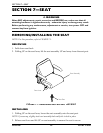
7. Reinstall the seat assembly onto the scooter. Refer to Removing/Installing the Seat on
page 34.
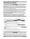
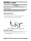
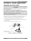
90° SEAT SWIVEL ADJUSTMENT
ƽ WARNING
Ensure that seat is locked into the forward position BEFORE and DURING
operation of the scooter. Otherwise, injury to the user and/or damage to the
scooter may result.
ࣼ CAUTION
DO NOT use the seat swivel option when accessories are installed (such as safety
flag, crutch/cane holder, etc.) and the seat is mounted in lowest height adjustment
position. Otherwise, damage to the scooter may occur.
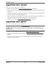
NOTE: For this procedure, refer to FIGURE 7.4.
1. The seat lever is located just beneath the seat on the RIGHT side.
2. Pull the seat lever UP to rotate the seat.
Mounting
Screws
Back Assembly
Seat Base
Mounting
Screws
Back Assembly
Seat Base
Mounting Screws
Back Assembly
Seat Base
Mounting Screws
Back
Assembly
Seat Base
MOUNTING POSITIONS
Mounting Holes