


SECTION 6—OPERATION OF THE POWERED SCOOTER
Part No. 1118395 27 300 and 400
SECTION 6—OPERATION OF THE
POWERED SCOOTER
CONTROL PANEL
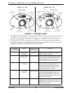
NOTE: For the following information, refer to FIGURE 6.1 and FIGURE 6.2.
1. SPEED CONTROL KNOB - Located on the TOP face of the control panel. The Turtle
icon represents the slowest speed and the Rabbit icon represents the fastest speed
(FIGURE 6.1).
2. BATTERY CHARGE INDICATOR (BCI) - The BCI is located on the TOP face of the
control panel as shown in FIGURE 6.1. The BCI is composed of eight (8) LED's - three
(3) GREEN, three (3) YELLOW and two (2) RED. It provides information on the
remaining battery charge. At full charge, all eight (8) LED's are lit. As the batteries
discharged, the number of LED's decrease from GREEN to YELLOW then RED. At
this level, the user should charge the batteries as soon as possible. Refer to the table on
the next page.
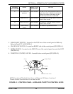
NOTE: The number of LED's bars may decrease when driving over uneven surfaces even with
batteries fully charged. To see an accurate true reading, insert the key and turn to the ON position
while the powered scooter is stationary.
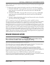
ƽ WARNING
When negotiating ramps, if the throttle control lever is released while in FOR-
WARD motion, the powered scooter will ROLL BACK approximately one (1) foot
before brake engages. If the throttle control lever is released while in REVERSE
motion the powered scooter will ROLL BACK approximately three (3) feet before
brake engages.